Section5: Maintenance
_ efore inspecting, cleaning or servicingthe machine, shutoff engine, wait for all movingpartsto come I
to a completestop, disconnectspark plug wire and move wire away from spark plug. Remove ignition I
key, if soequipped.
Fa ureto fo owthese nstructonscan resut nser ouspersona njuryor propertydamage.
Single Tine Replacement
The tines or tine hood edges may be
sharp. Wear thick gloves to protect
yourhandsfrom cutsor scrapes.
1. Move the Wheels/Tines/PTODrive
Leverto NEUTRAL,the WheelSpeed
Leverto either FASTor SLOWposition,
and theTines/PTOClutch Leverto
ENGAGE.
2. Gently tilt the tiller forward until the
enginerestson the ground.
3. Raisethe hoodflap at the backof the
tiller andtie it up with string.
4. Beforeremoving atine, note in which
directionthe benttip points. The newtine
must beinstalled in thesamedirection.
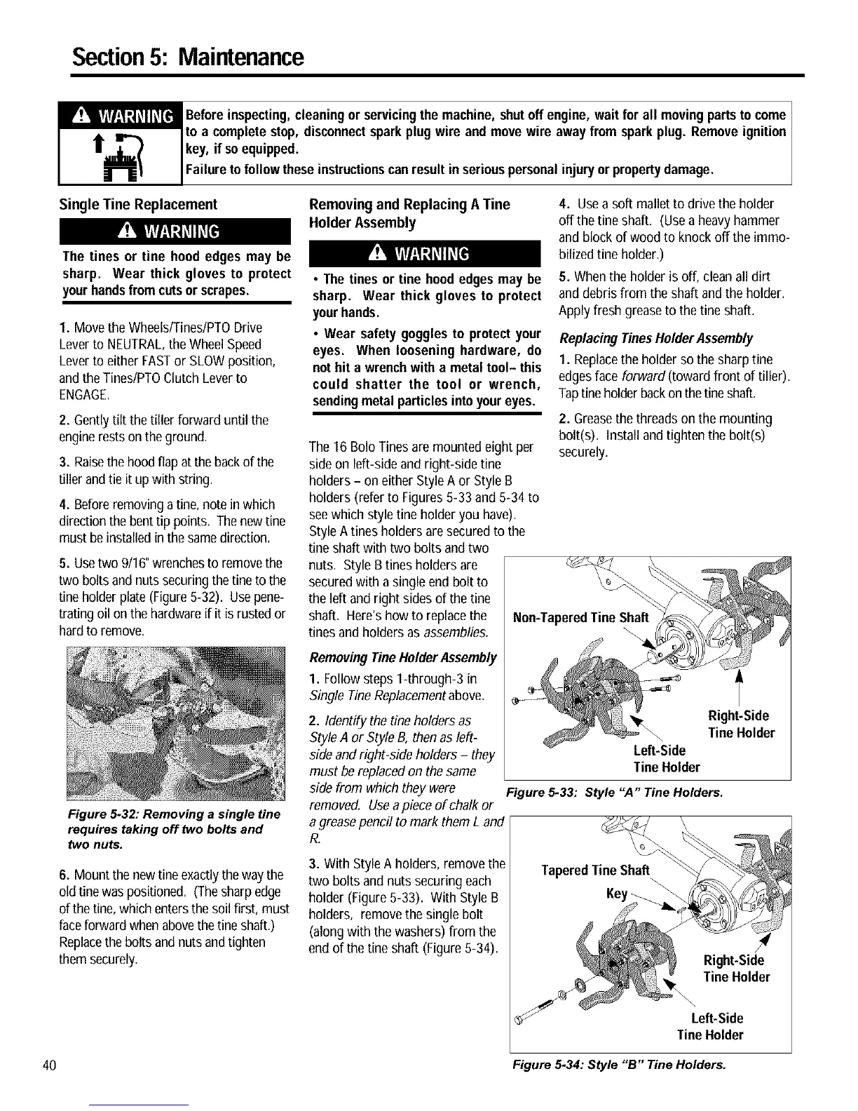
5. Usetwo 9/16"wrenchesto removethe
two boltsand nuts securing thefine tothe
tineholder plate (Figure5-32). Usepene-
trating oil onthehardware if it is rustedor
hardto remove.
Figure 5-32: Removing a single tine
requires taking off lwo bolts and
lwo nuts.
6. Mount the newfine exactlytheway the
old tinewas positioned. (Thesharp edge
ofthe fine,which entersthesoil first, must
faceforward whenabovethetineshaft.)
Replacethe bolts and nuts andtighten
them securely.
Removingand ReplacingA Tine
HolderAssembly
• The tines or tine hood edgesmay be
sharp. Wear thick gloves to protect
yourhands.
• Wear safety goggles to protect your
eyes. When loosening hardware, do
nothit a wrenchwith a metal tool- this
could shatter the tool or wrench,
sendingmetal particlesintoyour eyes.
The16 Bolo Tinesare mounted eight per
side on left-sideand right-side fine
holders - on either StyleA or Style B
holders (refer to Figures 5-33 and 5-34 to
seewhich style tine holder you have).
Style A tines holders are securedto the
fine shaft with two bolts andtwo
nuts. Style Btines holders are
securedwith a single end bolt to
the left and right sides of the tine
shaft. Here'show to replacethe
tines and holders as assemblies.
RemovingTine HolderAssembly
1. Follow steps 1-through-3 in
Single TineReplacementabove.
2. Identify the tine holders as
StyleA or Style B, thenas left-
side andright-side holders - they
must bereplaced on thesame
side from which they were
removed. Usea pieceof chalk or
a greasepencil to mark them L and
R.
3. With StyleA holders, remove the
two bolts and nuts securing each
holder (Figure5-33). With Style B
holders, removethe single bolt
(along with the washers) from the
end of the fine shaft (Figure5-34).
4. Usea soft mallet to drive the holder
off thetine shaft. (Usea heavy hammer
and block of wood to knock off the immo-
bilizedtine holder.)
5. When the holder is off, cleanall dirt
and debris from the shaft andthe holder.
Apply fresh greaseto the fine shaft.
Replacing TinesHolderAssembly
1. Replacethe holder sothe sharp tine
edgesface forward (toward front of tiller)=
Tapfine holderbackon thefine shaft.
2. Greasethe threads on the mounting
bolt(s). Installand tighten thebolt(s)
securely=
Non-TaperedTine Shaft
Right-Side
Tine Holder
Left-Side
TineHolder
Figure 5.33: Style "A" Tine Holders.
Right-Side
Tine Holder
Left-Side
TineHolder
49 Figure 5.34: Style "B" Tine Holders.



 To Next Page