Do you have a question about the Troy-Bilt 753 and is the answer not in the manual?
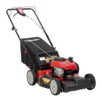
| Engine | Briggs & Stratton |
|---|---|
| Mulching Capability | Yes |
| Bagging Capability | Yes |
| Side Discharge Capability | Yes |
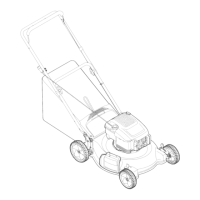
| Deck Size | 21 inches |
| Engine Type | Gasoline |
| Cutting Width | 21 inches |
| Cutting Height | 1.25 to 3.75 inches |
| Speed Settings | Variable |
Set a 1/8" gap between the spring and flat washer on the lift crank.
Measure distance between idler and drive pulleys with engine off and helper engaging blade drive.
Shorten the rod by one or two turns to ensure proper disengagement.
Remove Sems nuts and screws securing the brake pad to the idler arm.
Loosely install new brake pad and release control to engage sheave.
Remove hairpin clip and slide out the wheel drive control rod.
Loosen jam nut and thread rod clockwise for more tension.
Adjust brake locknut to achieve 3/8" to 5/16" gap with operator presence control released.
Place shift lever in neutral detent position and check for free rolling.
Remove shoulder bolts, washers, and locknuts securing deck to lift assemblies.
Remove the four screws securing the belt cover.
Remove blade drive belt and wheel drive belt.
Loosen locknuts, flat washers, and screws securing transmission to frame.
Remove the transmission from the unit for service.
Remove the two flange screws that secure the flap bracket.