7
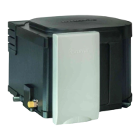
5. Fasten sealing frame (3) to the cowl body using 4 self-cutting
screws (4).
4
3
Screw the sealing frame
(3) in contact together
with the cowl body (1) so the
anti-twist device projects out!
6. Seal the gap between the hole (6) and the condensation
tube (7) with non hardening mastic – do not use silicone!
7. Mount the grille (8). Press the entire cowl assembly onto the
vehicle wall and fasten with 6 screws (5).
8. Screw the boiler securely to the floor of the vehicle with
at least two shackle plates (9) with the screws provided,
B 5.5 x 25, on suitable base (plywood panel, laminated wood
strips or metal base).
Water connection
All pressure and submergible waterpumps can be used for
operating the water heater.
In order to guarantee complete emptying of the
water content and to prevent pressures of greater
than 400 kPa occurring in the boiler, the enclosed pres-
sure reducer (10), the enclosed water connectors (12 +
13) and the enclosed safety (pressure relief) drain valve
(14) must be used!
12
13
14
10
The supplied water connectors (12 + 13) and safety/drain
valve (14) have a 12 mm rigid piping connection (e.g.
John Guest System). For connecting to rigid pipes with other
diameters appropiate adapters (not included in scope of
delivery) must be used.
As special accessories Truma supplies the water connectors
(12 + 13) and safety/drain valve (14) with a 10 mm / 3/8“
diameter hose nipple (please refer to the last page).
Route water pipes so that they are as short and free of
kinks as possible (hose connections must be secured
using hose clamps – also for cold water! – pressures of up
to 400 kPa can occur in the safety/drain valve – also with sub-
mergible pumps – because of the heat of the water and the
resulting expansion).
All hot water pipes should be routed in a descending
manner to the safety/drain valve! Otherwise no guaran-
tee of protection from frost!
Installation of the elbow water connectors
Screw elbow with integrated
breather valve (12) to hot
water connection pipe (up-
per pipe) and elbow without
breather valve (13) to cold
water connecting pipe (lower
pipe).
Slide on nut (17), tension
ring (18) and O-ring (19). As-
semble screw connector and
connecting pipe and fasten
together using nut (17).
Slide ventilation hose with
11 mm outer diameter (20)
onto the breather valve hose
nozzle (21) and route towards
the outside. Do not allow the
radius of the arc to be less
than 40 mm.
Cut off the ventilation hose
approx. 20 mm below the
floor of the vehicle at an
angle of 45° to the direction
of travel.
Installation of the safety (pressure relief)
drain valve
Ø 18 mm
14
Install the safety/drain valve
(14) at a place which is eas-
ily accessible, near the wa-
ter heater. Drill a hole with
18 mm diameter and pass
through the discharge tube.
Fasten safety/drain valve with
two screws. The draining is to
be directly to the outside at
a position protected against
splash water (apply splash
guard, if necessary).
Installation of the pressure reducer
10
The pressure reducer (10)
must be fitted between the
safety/drain valve and water
pump in accordance to the
direction of flow. Fasten the
pressure reducer to the floor.
Direction of travel
 Loading...