9
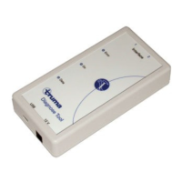
Truma Diagnose Tool
Symbols used
Symbol indicates a possible hazard.
Comment including information and tips.
Table of contents
Symbols used ........................................................................ 9
Safety instructions .......................................................... 10
Interface “Diagnose Tool”
Delivery scope ..................................................................... 10
System requirements .......................................................... 10
Install software .................................................................... 10
Operating voltage ................................................................ 10
Update software ................................................................. 10
LED display .......................................................................... 11
Connection (devices, control systems)
Combi ................................................................................ 11
Control unit installed in the heater ...................................... 11
Export control unit separately ............................................. 12
Mover® ............................................................................... 12
Control unit installed in the vehicle ..................................... 12
Export control unit separately ............................................. 12
Operation instructions (software)
Intended use ........................................................................ 13
User interface ...................................................................... 13
Set language ....................................................................... 13
“Diagnose Tool” program
Start program ...................................................................... 13
Search for device ................................................................ 13
Read error memory ............................................................. 13
Display error list / list of actions .......................................... 14
Save error list ...................................................................... 14
Reset errors ......................................................................... 14
End program ....................................................................... 14
Unlock ................................................................................ 14
Recognition of locked / unlocked control unit .................... 14
“Live Display” program
Start program ...................................................................... 15
Search for device ................................................................ 15
Show error detail ................................................................. 15
Set operating status ............................................................ 15
End program ....................................................................... 15

 Loading...