11
Connection (devices, control systems)
Observe the ESD-regulations!
Combi
Control unit installed in the heater
Room temperature control device at position 1 (= turned all
the way to the left).
Switch on control panel – heating without controlled
water temperature.
Combi 4 (E) / 6 (E): To prevent any malfunctions of the pro-
gram due to ignition sparks, the “Diagnose Tool” may only be
connected after the device has started.
Connect the “Diagnose Tool” to the Combi adapter cable.
Connection to Combi 4 (E) / Combi 6 (E) /
Combi D
X1 Coupling RJ12 for cable extension
Export error memory
Start the “Diagnose Tool” program on the computer
For Combi 4 E / 6 E, disconnect power selector switch!
–
–
–
–
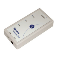
LED display
1 Error – red LED
Gives the manufacturer
information about the data
traffic.
2 On – green LED
Shines
USB connection and oper-
ating voltage available.
Flashes once
(1 Hz) operating voltage
via interface 1(2) missing.
Flashes (1 Hz, 0.5 s off / on)
USB connection missing.
(connect / test cable)
3 Data – yellow LED
Signalises the data transfer
on the bus.
–
–
–
–
–