2
BGA 14 / BGEA 14 LPG (Propane) and 230 V / 240 V Electric Storage Water Heater
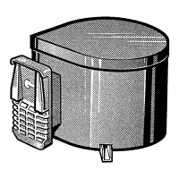
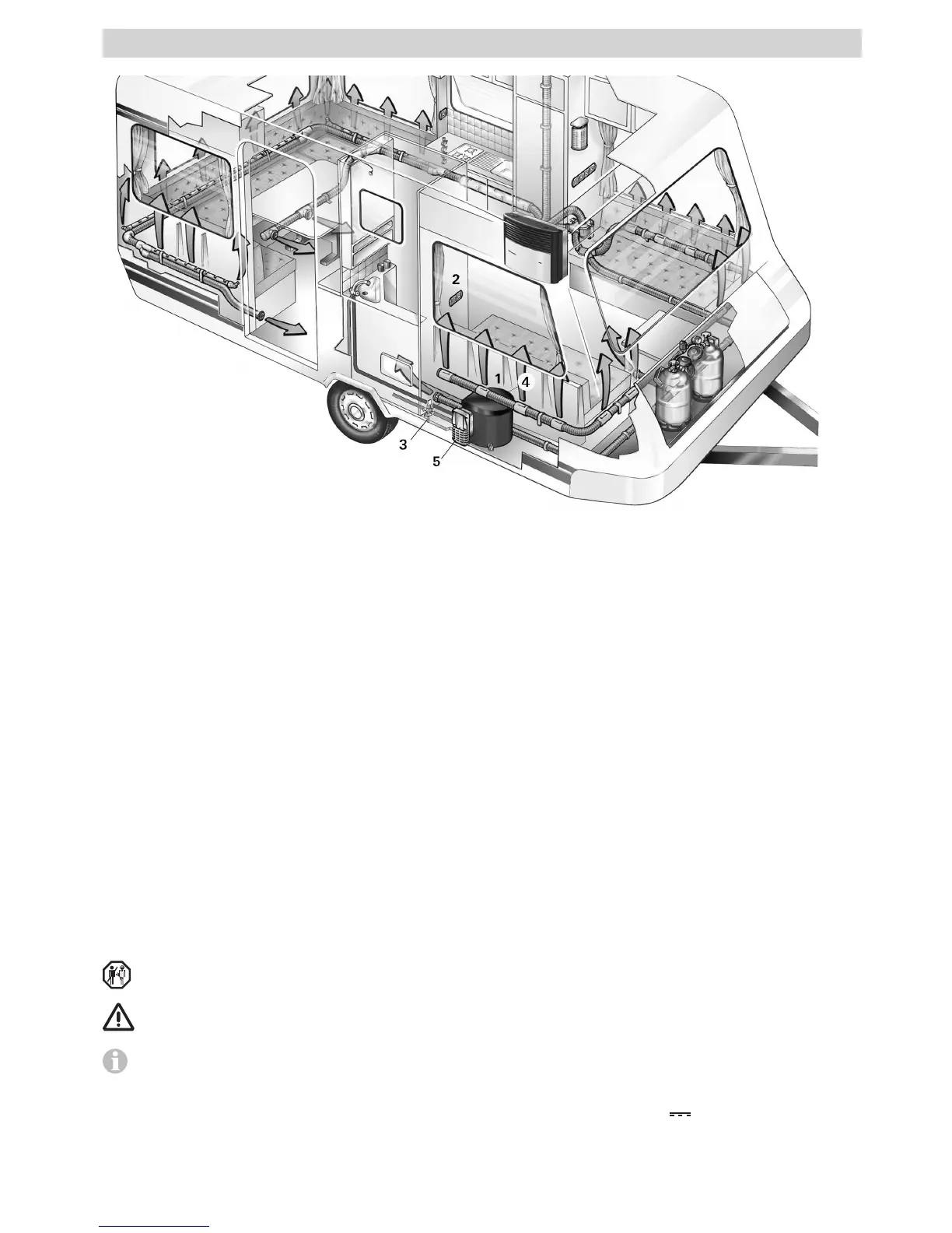
Installation example
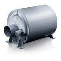
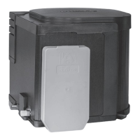
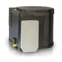
1 Truma UltraRapid HWS
2 Control panel
3 Drain valve
4 Pressure and Temperature Relief Valve (P&T safety valve)
5 Cowl for combustion air intake and exhaust gas discharge
Table of contents
Symbols used ........................................................................ 2
Model .................................................................................... 2
General safety notes ......................................................... 3
Operating instructions
Filling the Truma UltraRapid HWS with water ...................... 4
Pressure and Temperature Relief Valve (P&T safety valve) ... 4
Draining the water heater ..................................................... 4
Switching on gas operation .................................................. 5
Switching off gas operation .................................................. 5
Red indicator lamp “Fault“ .................................................... 5
Electrical operation 230 V ~ / 240 V ~ – option – ......... 5
Maintenance ....................................................................... 5
Fuses ..................................................................................... 5
Fault finding ........................................................................ 6
Technical data ..................................................................... 6
Truma warranty policy ..................................................... 7
Installation instructions
Data label .............................................................................. 8
Intended use .......................................................................... 8
Regulations ........................................................................... 8
Water heater kit ................................................................. 8
Choice of location .............................................................. 8
Installation of the water heater ............................................. 8
Water connection .............................................................. 9
Instructions for a proper water system ................................. 9
Installation of the pressure reducer ...................................... 9
Installation of the drain valve .............................................. 10
Mounting of the discharge pipe .......................................... 10
Installation of the elbow water connectors ........................ 10
Water pipe routing .............................................................. 10
Gas connection ................................................................. 11
Installation of the control panel .................................... 11
Electrical connection 12 V
....................................... 11
Electrical connection 230 V ~ / 240 V ~ – option – .... 12
Function check ................................................................. 12
Accessories ....................................................................... 12
Wiring Diagram ................................................................ 14
Symbols used
The device must only be installed and repaired by an
expert.
Symbol indicates a possible hazard.
Note containing information and tips.
Model
Truma UltraRapid Gas BGA 14
Truma UltraRapid Gas / Electric BGEA 14
Fig. 1
 Loading...