9
Water connection
Instructions for a proper water system
– All pressure and submergible waterpumps can be used for
operating the water heater.
In order to guarantee complete emptying of the
water and to prevent pressures of greater than
the maximum working water pressure occurring in the
Truma UltraRapid HWS, the enclosed pressure reduc-
er (10), water connectors (12 + 13), drain valve (14) and
P&T safety valve (23) must be used!
When using pressure pumps with high switching hysteresis,
hot water may flow back through the cold water tap. To pre-
vent backflow, we recommend that a non-return valve (nrv –
not included in the scope of supply) be fitted between the
outlet to the cold water tap and the drain valve.
nrv
14
10
16
23
15
22
13
12
Fig. 13
The supplied water connectors (12 + 13) and the drain
valve (14) have a 12 mm rigid piping connection (e. g.
John Guest System). For connecting to rigid pipes with other
diameters appropiate adapters (not included in scope of deliv-
ery) must be used.
– Route water pipes so that they are as short and free of kinks
as possible (hose connections must be secured using hose
clamps – also for cold water! – pressures of up
to 450 kPa can occur in the drain valve – also with
submergible pumps – because of the heat of the water and
the resulting expansion).
– All hot water pipes should be routed in a descending man-
ner to the drain valve! Otherwise there is no guarantee of
protection from frost!
Installation of the pressure reducer
Depending on the scope of supply – pressure reducer A or B
has to be installed.
For characteristics of the pressure reducer – see „Water
pressure reducer“ page 6.
Pressure reducer A
The pressure reducer (10) must be fitted between the drain
valve and water pump in accordance with the direction of
flow (indicated by arrow).
Fasten the pressure reducer to the floor.
10
2 x
Fig. 14
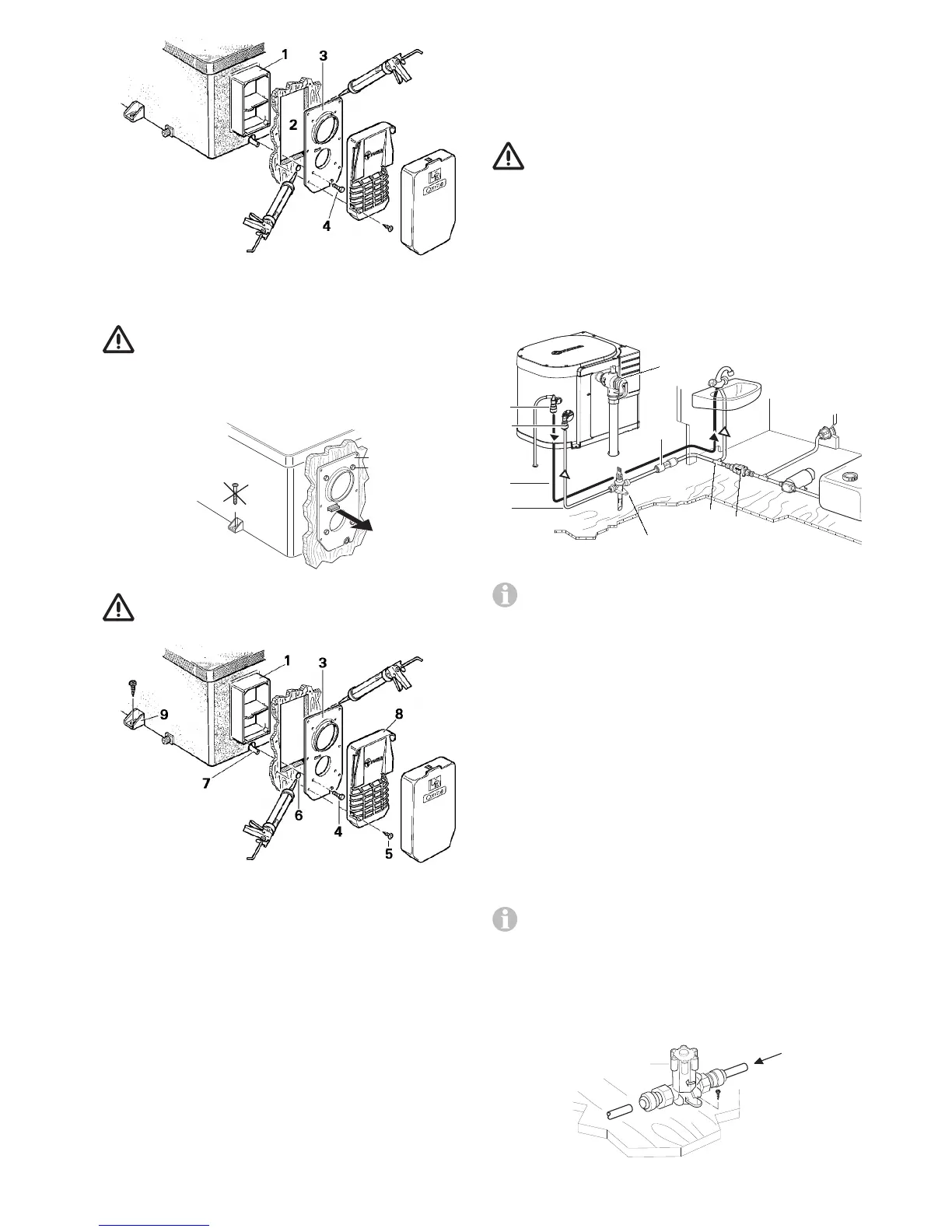
Fig. 10
Remove sealing frame (3) and coat with non-hardening
mastic on the side facing the vehicle – do not use silicone!
The sealing frame must be well sealed with respect to
the front sides and the cross bars of the cowl body (1)
as well as towards the outside wall!
Fasten sealing frame (3) to the cowl body using 4 self-tapping
screws (4).
4
3
Fig. 11
Screw the sealing frame (3) together with the cowl
body (1) so the anti-twist device projects.
Fig. 12
Seal the gap between the hole (6) and the condensation tube (7)
with non-hardening mastic – do not use silicone!
Mount the grille (8). Press the entire cowl assembly onto the
vehicle wall and fasten with 6 screws (5).
Screw the Truma UltraRapid HWS securely to the floor of the
vehicle with at least two shackle plates (9) with the screws
provided, B 5.5 x 25, on suitable base (plywood panel, lami-
nated wood strips or metal base).

 Loading...