Step 1:
A. Place the product in the area it will be used.
a. Note: The elliptical must be placed on a level surface
B. Remove the Elliptical from the packaging
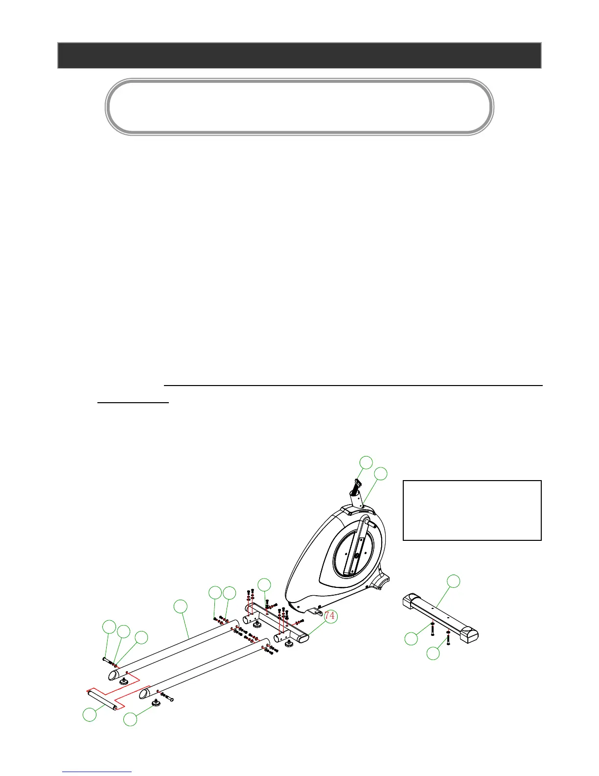
C. Attach the front stabilizer (35) to the main frame (47) using 2 x M8*55mm Allen bolts (33)
and 2 x Ф8*19*1.5mm flat washer (34).
D. Rotate the attach the slider tubes (104) to the rear stabilizer (74) using 12 x M8*20mm
Allen bolts (17), 12 x Ф8 spring washers (20), and 12 x Ф8*19*1.5t curved washers
(16)
E. Attach the connecting tube (96) to the slider tubes (104) using 2 x M8*70mm Allen Bolts
(93), 2 x Ф8 spring washers (20), and 2 x Ф8*19*1.5t curved washers (16)
F. Attach the rear stabilizer (74) to the main frame (47) using 4x M8*20mm (17), 4 x Ф8
spring washers (20), 2 x Ф8*19*1.5t curved washers (16), and 2 x Ф8*19*1.5mm flat
washer (34). Note: the flat washers are used on the bolts attached through the top of the
rear stabilizer.
G. Tighten all bolts now.