EasyManua.ls Logo

TSI Instruments AIRFLOW Instruments ProHood PH720 User Manual

TSI Instruments AIRFLOW Instruments ProHood PH720
64 pages
To Next Page IconTo Next Page
Page #1 background imageLoading...
Page #1 background image
OWNER’S MANUAL
Alnor
®
Electronic Balancing Tool
Models EBT720/EBT721
and
AIRFLOW Instruments ProHood
Capture Hood Models PH720/PH721
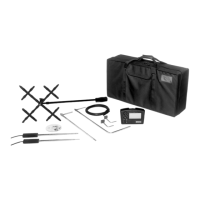
EBT720/PH720 Shown with all
accessory options
EBT721/PH721 Shown with
all accessory options

Table of Contents

Questions and Answers:

TSI Instruments AIRFLOW Instruments ProHood PH720 Specifications

General IconGeneral
ModelProHood PH720
Storage Temperature-4 to 140°F (-20 to 60°C)
TypeAirflow Instruments
Measurement Range25 to 2500 CFM
Accuracy±3% of reading
Operating Temperature40 to 122°F (4 to 50°C)
Battery Life10 hours
Battery TypeFour AA-size batteries (alkaline or rechargeable)
DisplayDigital LCD
Weight2.2 lb (1 kg)
Dimensions12.5 x 12.5 x 3.5 in (318 x 318 x 89 mm)
Probe LengthNot applicable
Probe DiameterNot applicable
Airflow Range85 to 2, 550 m3/h (50 to 1, 500 cfm)

Summary

Chapter 1. Introduction

Instrument Description

Overview of the Alnor EBT720/EBT721 and AIRFLOW PH720/PH721 instruments and their features.

Standard Tools

Descriptions of essential tools like Pitot tubes and static pressure probes for measurements.

Optional Tools

Descriptions of accessories like capture hoods and probes for enhanced measurements.

Chapter 2. Unpacking and Setting Up

Unpacking the Instrument

Instructions for unpacking the instrument and checking components against the packing list.

Preparing the Instrument for Use

Guidance on powering the micromanometer using AC adapter or batteries.

Connecting the Pitot Tube

Procedure to connect the pitot tube to the micromanometer's pressure ports.

Connecting the Static Pressure Port

Procedure to connect the static pressure probe to the micromanometer.

Attaching the Micromanometer to the Capture Hood Base

Steps for securely mounting the micromanometer onto the capture hood base.

Connecting the Velocity Matrix

Procedure to connect the velocity matrix to the micromanometer's positive and negative ports.

Connecting the Air Flow Probe

Procedure to connect the air flow probe to the micromanometer.

Connecting Temperature/Humidity Probes

Steps for connecting temperature or temperature/humidity probes to the micromanometer.

Chapter 3. Getting Started

Keypad Operation

Explanation of the function and use of each key on the micromanometer keypad.

Common Terms

Definitions of key terms used in the manual, such as Sample, Logging Interval, and Test ID.

Step-By-Step Example Operation

A practical guide to taking sample pressure readings with the instrument.

Chapter 4. How To

Select Measurement Tool

Guide to selecting the appropriate measurement device or tool for the task.

Configure Instrument Operation and Data

Set time, date, units, parameters, logging, display modes, and manage sample data.

Configure Communication and Data Transfer

Set RS232 output, baud rate, format, and download data to printers or computers.

Perform Instrument Calibration

Guide to user and factory calibration procedures for accurate measurements.

Chapter 5. Changing Flow Hoods

Flow Hood Parts Identification

Identification and description of the components of the capture hood assembly.

Hood Assembly and Installation

Instructions for assembling and installing different sizes of capture hoods.

BSC Hood Assembly

Detailed steps for assembling the direct inflow measurement hood for biological safety cabinets.

Chapter 6. Flow Measurements Using the Capture Hood

Non-Backpressure Compensated Measurements

Methods for taking flow measurements without backpressure compensation.

Backpressure Compensated Measurements

Procedure for taking flow measurements with backpressure compensation enabled.

Error Display and Handling

Explanation of error messages and how to handle them during measurements.

Chapter 7. Maintenance and Troubleshooting

Component Cleaning Procedures

Guidelines for cleaning the fabric hood, micromanometer, manifold, and cases.

Instrument Calibration Services

Information on recommended annual calibration and shipping procedures.

Troubleshooting the Instrument

Lists symptoms, possible causes, and corrective actions for instrument malfunctions.

Understanding Error Codes

Explanation of error codes, their causes, and recommended actions.

Appendix A. Back Pressure

Understanding Back Pressure Effects

Explanation of how capture hood placement affects air flow and measurement.

Verifying Flow Measurements

Recommended practices for validating capture hood measurements using velocity traverses.

Appendix B. Actual vs. Standard Air Velocity and Flow Measurements

Related product manuals