TSI Incorporated – Visit our website www.tsi.com for more information.
USA Tel: +1 800 874 2811
UK Tel: +44 149 4 459200
France Tel: +33 4 91 11 87 64
Germany Tel: +49 241 523030
India Tel: +91 80 67877200
China Tel: +86 10 8219 7688
Singapore Tel: +65 6595 6388
P/N 6006775 Rev A ©2013 TSI Incorporated Printed in U.S.A.
Attaching the Hoses to the Manometer
Connect the straight female flare fitting on the High pressure (red) hose to the male fitting on the top of the
manometer marked with a plus (+) sign. Connect the straight female flare fitting on the Low pressure (blue) hose
to the male fitting on the top of the manometer marked with a minus (-) sign.
Bleeding Entrained Air from the Hoses
1. Turn the shut-off ball valve on both the High and Low pressure hoses to the closed position.
2. Turn the valve handle on the manometer to the MEASURE position.
3. Using an appropriate fitting, connect the open end of the High pressure (red) hose to the test point with the
higher line pressure.
4. Attach the appropriate fitting to the open end of the Low pressure (blue) hose.
5. To ensure all the air is bled from the hoses, hold the open end of the Low pressure (blue) hose in an upright
position over a suitable receptacle or near a drain.
6. Turn the shut-off ball valve on both the High and Low pressure hoses to the open position.
7. Turn the valve handle on the manometer to the BYPASS position to allow the liquid flow to displace the
entrained air.
8. Once the liquid is flowing steadily from the Low pressure (blue) hose, turn the valve handle on the manometer
to the MEASURE position.
Performing Pressure Measurements
The HM675 Hydronic Manometer allows for simultaneous and continuous measurement and display of the High-
side gauge and Differential pressure. The calculated Low-side gauge pressure is also displayed.
Discrete Pressure Measurements
Taking a discrete pressure measurement provides a single time-averaged reading taken over the sampling period
as defined by the current time constant setting when the READ key is pressed. Discrete pressure measurement
values are displayed on-screen for a period of 10 seconds and then returns to continuous measurement mode.
Performing Temperature Measurements
The accessory temperature probes are optional for the HM675 Hydronic Manometer and can be connected to the
3-pin mating connector located on the right-hand side of the manometer. The unit of measurement for
temperature (°F or °C) is driven by the differential pressure measurement:
Differential pressure in psi, inH
2
O, ftH
2
O, or inHg → temperature in °F
Differential pressure in kPa, mH
2
O, mmHg, or bar → temperature in °C
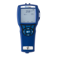
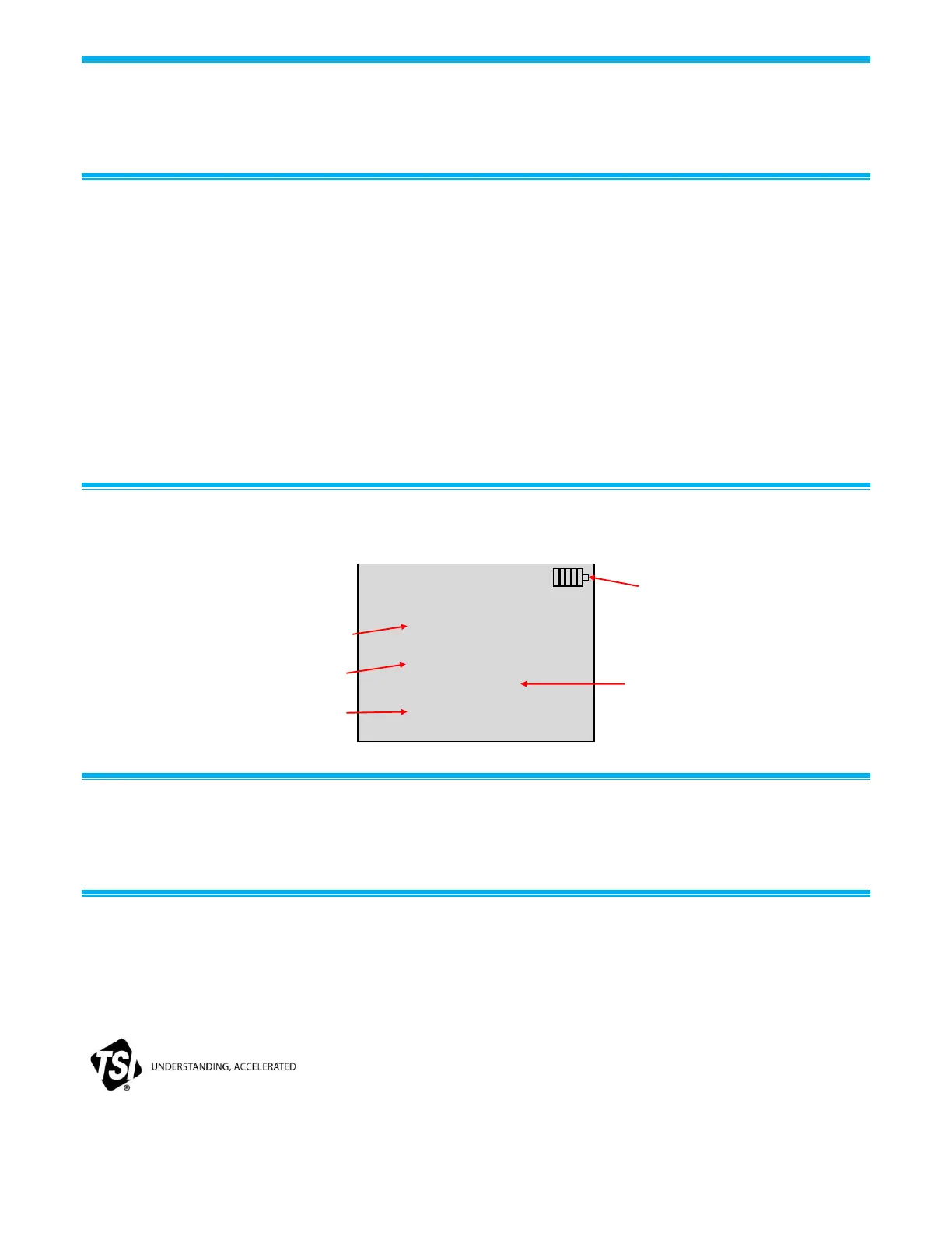
Time Constant: 5 Seconds
0.00ft.H2O dP
0.00 ft.H2O High
0.00 ft.H2O Low
70.0°F Probe1
70.0°F Probe2
High Side
Pressure
Low Side
Pressure
Temperature
Differential
Pressure
Battery
Status