13
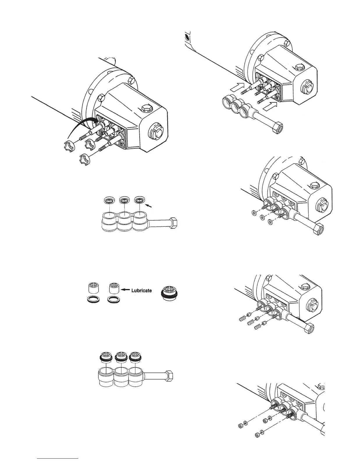
REASSEMBY OF THE SEAL ASSEMBLY
1. Examine seal retainers and replace if worn
or damaged. Install on plunger rod and press
into crankcase with tabs out. (Figure A)
2. Place inlet manifold on work surface with
small I.D. ports up. (Figure B)
3. Lubricate new low
pressure seal and
press into position
in the manifold
chambers with
garter spring
down. (Figure B)
4. Carefully examine plungers for scoring or
cracks and replace if worn. Next lubricate ce-
ramic plungers and new high pressure seals.
Place the
deeper
recessed
hole of the
plunger into
the metal back side of the seal and slide
seal to the middle of the plunger. (Figure C)
5. Place inlet manifold on work surface with
larger I.D. ports up. Install plungers with
seals into ports
with metal seal
side into mani-
fold.
Press into posi-
tion using the larger I.D. end of discharge
adapter-seat. (Fig. D)
6. Carefully install manifold over plunger rod
ends and slowly press into crankcase.
(Figure E)
7. Examine inlet valve and replace if worn.
Inlet valve cannot be lapped or reversed
if worn. Install
new inlet
valve with
ridged side
facing away
from the
crankcase,
toward the
discharge.
(Figure F)
8. Examine spacers for wear and replace as
needed. Install spacer on each plunger
with smaller outside diameter (O.D.)
into inlet valve.
9. Examine
springs for
damage or
fatigue and
replace as
needed.
Place on
plunger
rods. (Figure G)
10.Install washers next with concave side
toward manifold.
11. Next install nuts and torque to specifica-
tions in TORQUE CHART. (Figure H)
Figure A
Figure E
Figure F
Figure G
Figure H
Figure B
Figure C
Figure D
Note: Position with
garter spring down.