14
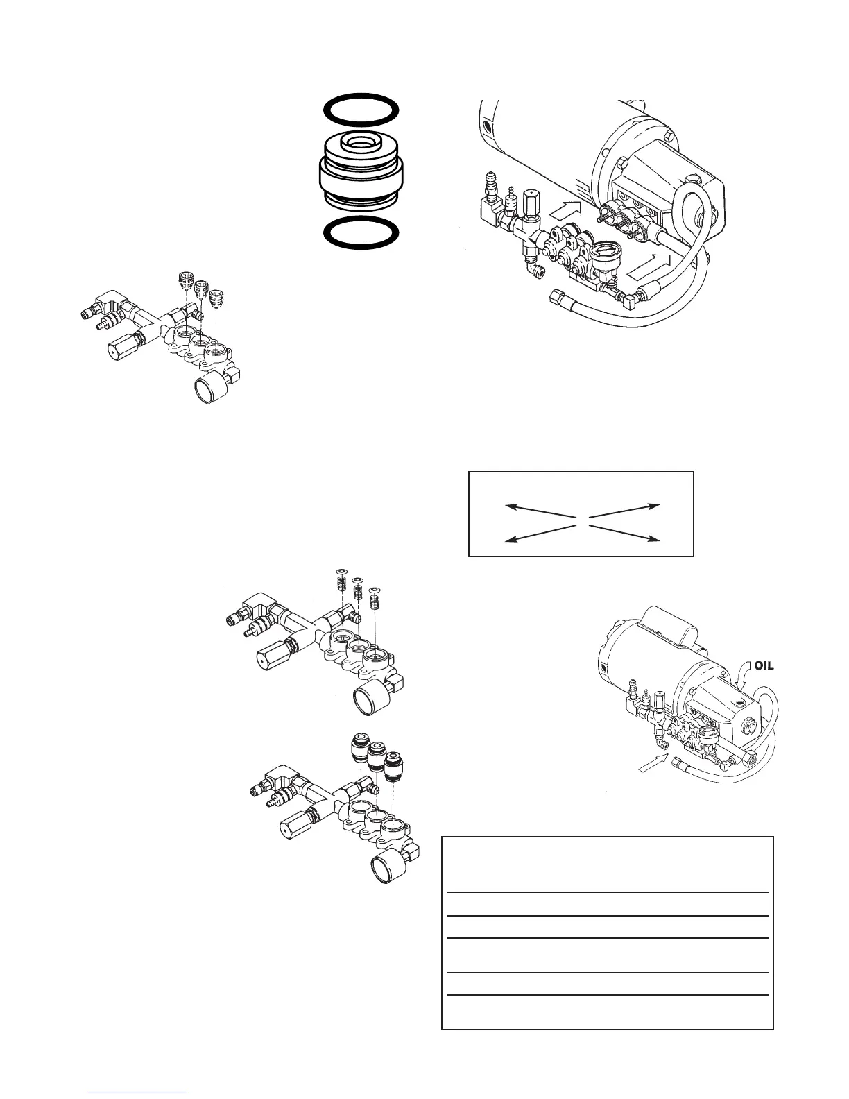
REASSEMBY OF THE DISCHARGE VALVE ASSEMBLY
1. Examine discharge adapter-
seat o-rings and replace if
worn. Lubricate and install
o-rings on both front and
rear of adapter-seat.
(Figure A)
2. Place discharge
manifold on work
surface and install
valve retainers in
each port with top
tab down and
completely seat
into the chamber.
(Figure B)
3. Replace worn or damaged springs and
place into retainers.
4. Examine valves and seats for pitting,
grooves or wear and replace as needed.
5. Place valves
over springs
with concave
side down.
(Figure C)
6. Lubricate O.D.
of discharge
adapter-seat and
insert smaller I.D.
into discharge
manifold ports.
Snap into position.
Exercise caution
not to cut or pinch
o-rings. (Figure D)
7. Carefully guide manifold with adapters
over plunger rod ends and press into inlet
manifold. (Figure E)
8. Replace six (6) socket head screws and
torque to specifications. See TORQUE
CHART below. Torque diagonally in order
shown. The outer four (4) screws, then
center two (2), hand tight. Then repeat
series to specifications. (Figure F)
9. Reattach by-pass hose to bottom of
unloader fitting.
10.Remember to fill
crankcase with
oil before replac-
ing top
cover to unit.
See “LUBRICATION”
for more information.
(Figure G)
Torque Sequence
153
462
↕
Torque Chart
Tool Torque
Pump Item Thread Size in.lbs. ft.lbs. Nm
Outer Bearing Case M6x16 M10 50 4.0 6.0
Inner Bearing Case M6x16 Phillips 50 4.0 6.0
Manifold Socket M8x75 M6 115 9.4 13
Head Screws
Plunger Rod Nuts M6 M10 55 4.4 6.2
Oil Gauge M28 Oil Gauge 45 3.6 5
Tool
Figure A
Figure B
Figure C
Figure E
Figure F
Figure G
Figure D