Manual Tulp gas fires EN
P. 12
3.3.1 Building the Fireplace
Construct a studwork fireplace to the desired sizes, minimum sizes are shown in section 3.3.2. Any
combustible material used to construct the Fireplace must not be closer than the minimum dimensions
quoted in section 3.3 above. These dimensions must be observed even if the frame work will be
protected by non-combustible material.
!!! Do not use insulation material (or other) to pack the void around or above the appliance.
!!! Provide ventilation from the fireplace to the minimum amount quoted in 3.3 above.
!!! Provide a cut-out for the Control Access Door.
3.3.2 Built-In Fireplace Sizing
For the sizing of the fireplace we would like to refer to the drawings of the appliances (in the end of
this manual). Also the dimensions of the access door you can find there.
Please look closely at the following points:
Make sure there is a min gap of 2 mm between the appliance and the plasterwork. It is possible
that the appliance expands a bit. If the appliance is built in too tight, the plasterwork will crack.
Take care of enough air inlet (bottom) and outlet (top) in the Fireplace/column. Please look at
paragraph 3.3.
Make sure that the back of the appliance is not against a wall. There should be a gap of at least
50 mm!!
3.4 Flue Connection
3.4.1 General notes
This appliance may be installed with a roof terminal (C31) or a wall terminal (C11).
This appliance may only be used with Balanced Flue (otherwise known as Concentric Flue) parts as
specified by Tulp. The Tulp specified flue parts have been approved with the appliance. If the appliance
is installed on non-Tulp approved parts, Tulp cannot guarantee or accept and responsibility for the
proper and safe working of the appliance.
The flue system must be constructed from the appliance upwards, with all joints being fully locked and
sealed using the Tulp specified parts.
3.4.2 Locating the terminals
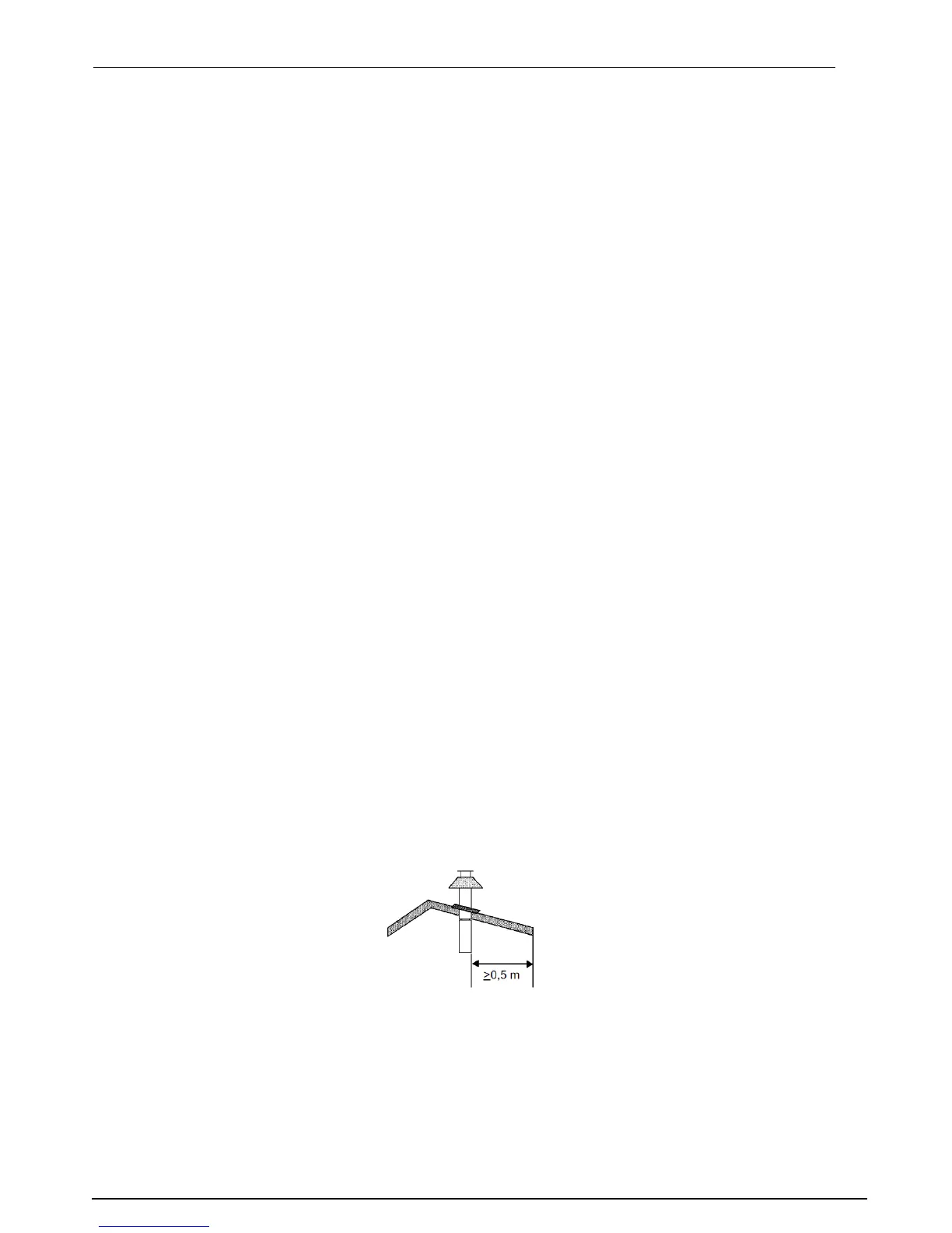
3.4.2.1 Location of the terminal on the roof (vertical).
There should be a minimal 0,5 meter distance between the terminal and the roof edge, with exception
of a possible present ridge edge.