31 Manchester Series MAN210-FG/MS121/MAN210-HC Rigging Manual
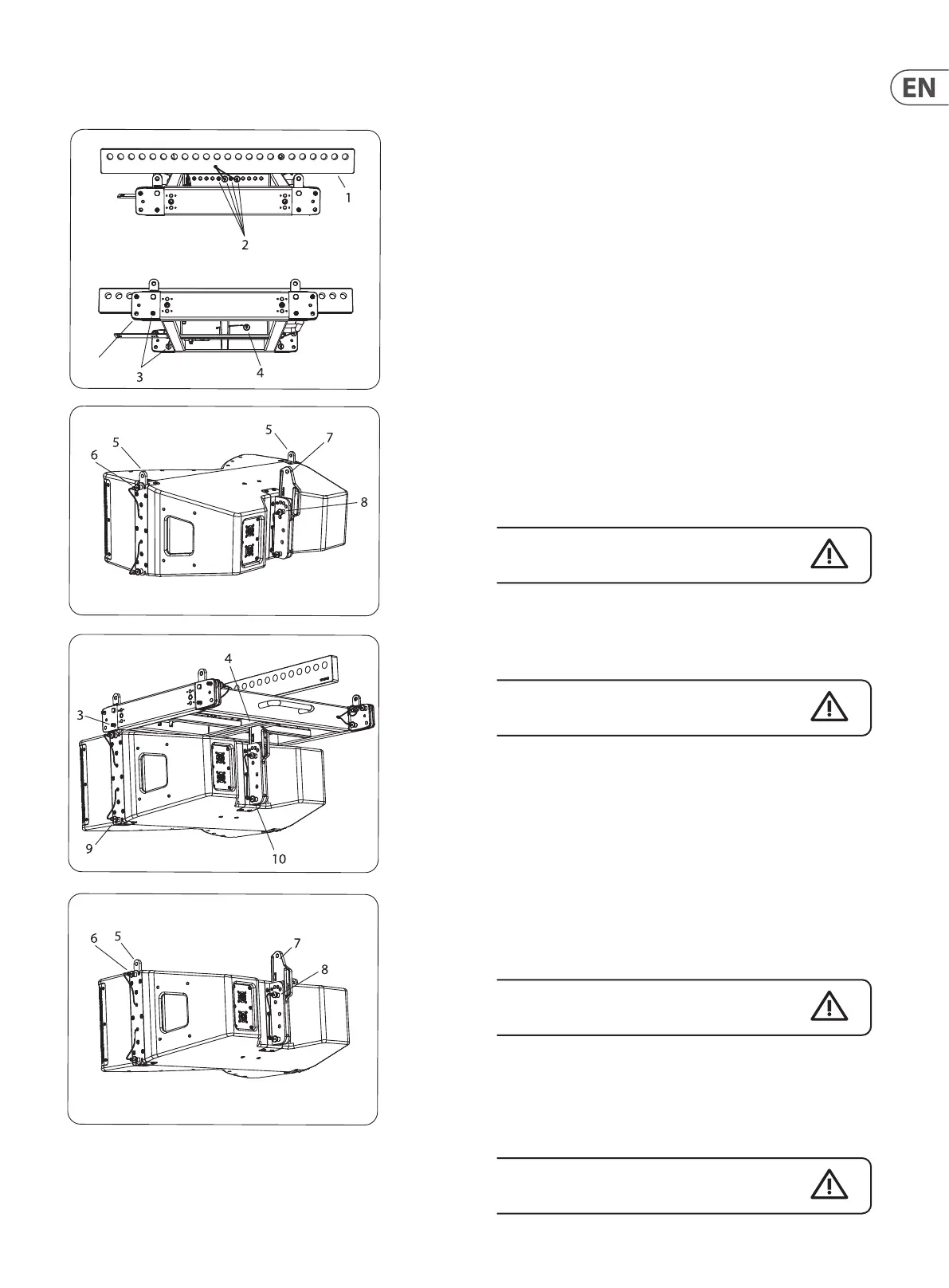
Procedure 3.1 Connecting MV210-HC Cabinets to the MAN210-FG
1. Install the Tip Bar (1) onto the MAN210-FG y grid and secure using the
4 rigging pins (2).
2. Double check that all pins are correctly inserted, before proceeding further.
3. Prepare the MAN210-FG by removing the 2 front rigging pins (3) and the rear
rigging pin (4).
4. Prepare all the MV210-HC cabinets, by pulling out the front rigging pins (6),
so the spring-loaded top links (5) will move to the up position. Reinsert the
pins (6) to secure the links in the up position. Remove the MV210-HC rear pin
(8) and slide the rear mounting plate (7) up. Reinsert the rear pin (8) of the
rst cabinet into the hole marked '7.5/15/FG' to secure the plate.
Note: The hole marked '7.5/15/FG' is used in order to set the rst cabinet
parallel to the y grid. This allows the MAN210-FG to serve as a visual
reference for checking array focus on the audience area, that is, if you can
see the top of the MAN210-FG then you are outside the vertical coverage
pattern of the array.
5. Carefully lift the MAN210-FG y grid on top of the rst MV210-HC cabinet
and align the front links (5) of the cabinet with the y grid holes where the
pins (3) were located. Note: the y grid front holes are not used, but the next
set. Reinsert the front pins (3) to secure the links (5) of the cabinet to the y
grid.
Take care not to trap your ngers between components.
6. Support the rear of the y grid and align the top hole of the MV210-HC rear
mounting plate (7) with the rear hole in the y grid spine. Reinsert the rear
pin (4) to secure the plate to the y grid.
Double check that all pins are correctly inserted,
before proceeding further.
7. Attach the bow shackles or other lifting equipment securely to the Tip Bar
mounting hole recommended by the EASE FOCUS 3 software, then attach
the hook and chain. Carefully raise the y grid/cabinet assembly to a
reasonable working height to allow attaching the next cabinet.
8. Remove the MV210-HC cabinet's front lower pins (9) and rear pin (10).
9. Prepare the next MV210-HC cabinet, as described in step 4.
10. Carefully lower the y grid/cabinet assembly until the top links (5) of the
lower cabinet t into the corresponding slots in the bottom of the top
cabinet. Insert the front two pins (9) of the top cabinet, to secure the links
(5) in the slots.
Take care not to trap your ngers between components.
11. Support the rear of the lower cabinet and align the hole of its rear mounting
plate (7) with the rear hole in the top cabinet. Insert the rear pin (10) to
secure the plate to the cabinet. The holes for pin 8 are marked with the angle
from 0 to 20 degrees. Choose the correct hole that corresponds to the angle
recommended by EASE FOCUS 3 software for this cabinet.
Double check that all pins are correctly inserted, before
proceeding further.
Not used
 Loading...