30 Manchester Series MAN210-FG/MS121/MAN210-HC Rigging Manual
3.0.1 Required Components
Item Quantity
MAN210-FG Fly Grid 1
MV210-HC Cabinet 13 (maximum at 10:1 Safety Factor)
3.0.2 Preparation
Use the EASE FOCUS 3 software application to design your system to suit the
venue. This will calculate which y grid mounting hole to attach your bow
shackle, and at which angle to set each MV210-HC cabinet to achieve optimum
coverage.
3.0.3 Location
Move the rst MV210-HC cabinet so it is sitting upright on a safe at surface,
directly below the suspension point.
3.0.4 Measured Weights
Item Quantity Weight
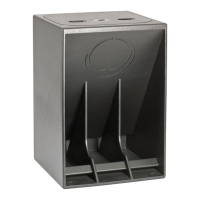
MAN210-FG with
Tip Bar
1 32.8 kg 72.3 lbs
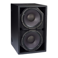
MV210-HC 1 35.5 kg 78.3 lbs
3.0.5 MAN210-FG Fly Grid WLL (10:1 Safety Factor)
Item Working Load Limit (WLL) 3 Point Suspension
MAN210-FG 495 kg 1091.3 lbs
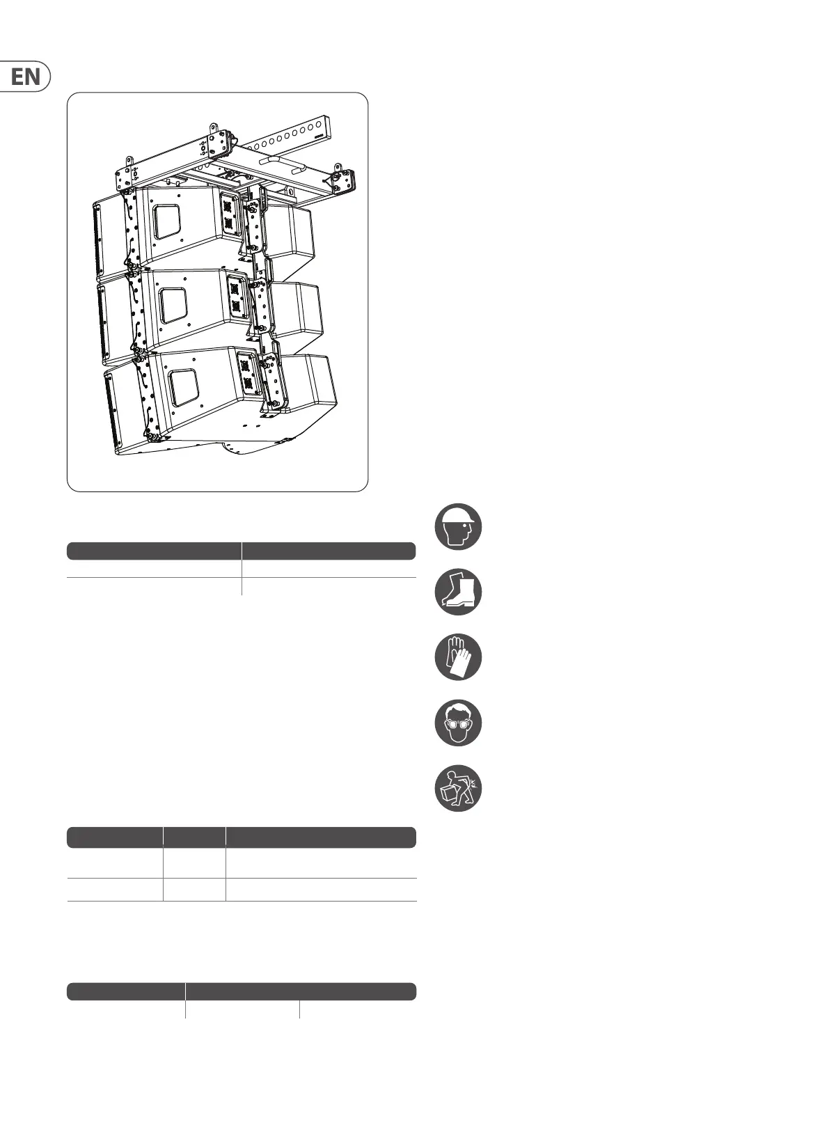
Chapter 3: Assembling an MV210-HC Array on a MAN210-FG Fly Grid
The following procedure shows how to build an array of MV210-HC cabinets
by adding them one at a time.
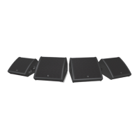
Alternatively, cabinets can be pre-assembled into groups of four, and then
connected to the y grid at a later time. This method is shown in procedure 3.2.
The system is suspended using a MAN210-FG y grid that attaches to your
lifting system.
The top MV210-HC cabinet connects to two front mounting points on the y grid,
and one rear mounting point.
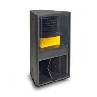
There are 9 holes on the rear sliding mounting plate of the MV210-HC that allow
the cabinet angle to be selected from 0 to 20 degrees.
! WARNING
DO NOT EXCEED A TOTAL QUANTITY OF 13 MV210-HC CABINETS FOR ONE
MAN210-FG FLY GRID. FAILURE TO FOLLOW INSTRUCTIONS MAY CAUSE
PERMANENT INJURY OR DEATH.
3.0.6 Personnel
The following procedures shall be undertaken by experienced, certied,
qualied, and authorised personnel only. The procedures require the use of three
or more authorised persons.
Protective Headwear shall be worn
Protective Footwear shall be worn
Protective Gloves shall be worn
Protective Eyewear shall be worn
Practice Safe Lifting
 Loading...