33 Manchester Series MAN210-FG/MS121/MAN210-HC Rigging Manual
Procedure 3.2: Adding a group of MV210-HC Cabinets to the MAN210-FG Fly Grid
Groups of MV210-HC cabinets can be pre-assembled using Procedure 3.1, steps 8
to 11, and then connected to the MAN210-FG y grid as an assembled group just
prior to ying.
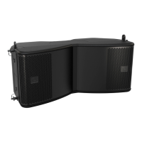
The MV210-HC cabinets connect to each other using the front mounting links (3),
and the rear mounting plate (5).
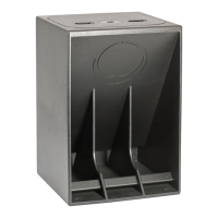
1. Prepare the MAN210-FG y grid by installing the Tip Bar with its 4 pins, and
by removing the MAN210-FG 2 front pins (1) and the rear pin (2).
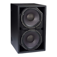
2. Prepare the top MV210-HC cabinet of the group, by pulling out the front
rigging pins (4), so the spring-loaded top links (3) will move to the up
position. Reinsert the pins (4) to secure the links in the up position. Remove
the MV210-HC rear pin (6) and slide the rear mounting plate (5) up. Insert the
rear pin (6) in the hole marked '7.5/15/FG' to secure the plate.
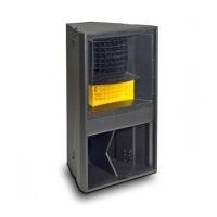
3. Carefully lift the MAN210-FG y grid onto the top MV210-HC cabinet and
align the front links (3) of the cabinet with the y grid holes where the pins
(1) were located. Note: the y grid front holes are not used, but the next set.
Reinsert the front pins (1) to secure the links (3) of the cabinet to the y grid.
Take care not to trap your ngers between components.
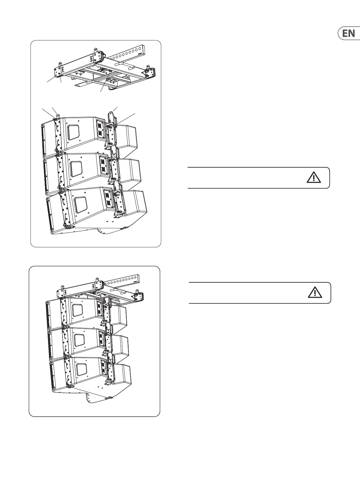
4. Support the rear of the y grid and align the y grid's rear mounting hole
with the top hole in the MV210-HC rear plate (5). Insert the y grid rear pin
(2) to secure the plate to the y grid.
Note: The '7.5/15/FG' hole is selected to attach the top MV210-HC cabinet to
the MAN210-FG, in order to set the angle of the top cabinet parallel to the y
grid. This allows the MAN210-FG to serve as a visual reference for checking
array focus on the audience area, that is, if you can see the top of the
MAN210-FG then you are outside the vertical coverage pattern of the array.
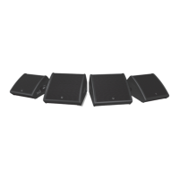
The angles of the other cabinets can be adjusted by supporting the cabinet
weight and moving the rear plates (5) of the various cabinets and inserting
the pins (6) into the desired angle holes.
Double check that all pins are correctly inserted.
! WARNING
DO NOT EXCEED A TOTAL QUANTITY OF 13 MV210-HC CABINETS FOR ONE
MAN210-FG FLY GRID. FAILURE TO FOLLOW INSTRUCTIONS MAY CAUSE
PERMANENT INJURY OR DEATH.
! WARNING
DO NOT FLY THE PRE-ASSEMBLED GROUPS OF MV210-HC CABINETS WITHOUT
THE MAN210-FG FLY GRID. FAILURE TO FOLLOW INSTRUCTIONS MAY CAUSE
PERMANENT INJURY OR DEATH.
NOTE
Disassembly is the reverse of assembly.
13 Maximum (10:1 Safety Factor)
1
Not used
2
3
4
5
6
 Loading...