36 Manchester Series MAN210-FG/MS121/MAN210-HC Rigging Manual
5
4
6
6
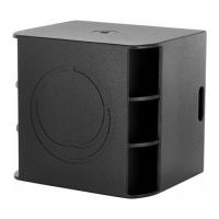
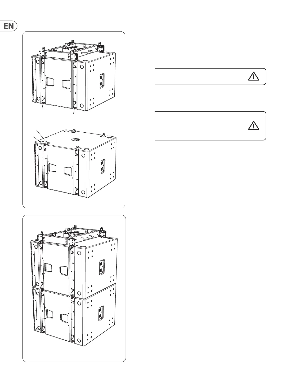
6. Prepare the upper subwoofer by removing its 4 lower pins (6).
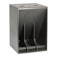
7. Prepare the lower subwoofer by pulling out its 4 top pins (4) so the top links
(5) spring up. Reinsert the top pins (4) to secure the links in the up position.
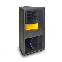
8. Carefully lower the upper subwoofer and y grid assembly onto the
lower subwoofer, and align the lower subwoofer's top links (5) with the
corresponding slots in the bottom of the upper subwoofer.
Take care not to trap your ngers between components.
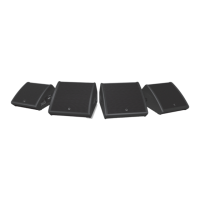
9. Insert the upper subwoofer's 4 lower pins (6) to secure the subwoofers
together.
Double check all the connections to make sure that the
MS121 subwoofers and the MAN210-FG y grid are securely
connected together.
10. The addition of one more MS121 subwoofer is performed by repeating steps
6 through 9.
! WARNING
DO NOT EXCEED A TOTAL QUANTITY OF 9 MS121 SUBWOOFERS FOR ONE
MAN210-FG FLY GRID. FAILURE TO FOLLOW INSTRUCTIONS MAY CAUSE
PERMANENT INJURY OR DEATH.
NOTE
Disassembly is the reverse of assembly.
 Loading...