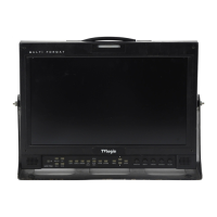
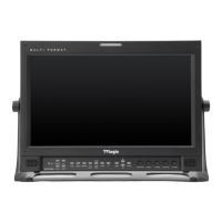
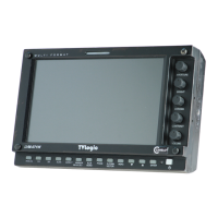
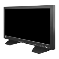
Multi Format LCD Monitor 21
● This product provides a REMOTE
CONTROL mode. The user may connect
RJ-45 jack to the REMOTE terminal on the
rear of the unit and designate a function
for each pin.
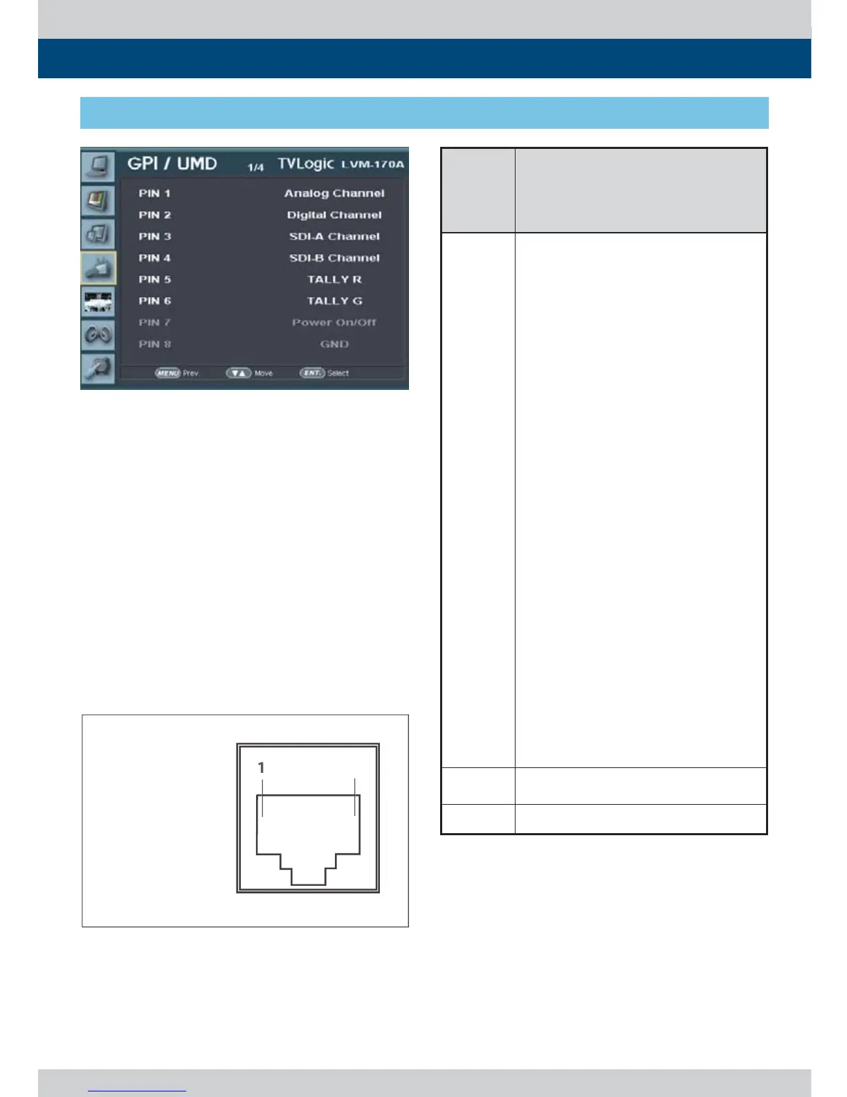
● The default settings are as follows :
PIN 1 : ANALOG Channel
PIN 2 : Digital Channel
PIN 3 : SDI-A Channel
PIN 4 : SDI-B Channel
PIN 5 : TALLY R
PIN 6 : TALLY G
PIN 7 is POWER ON/OFF use only, PIN 8 is GND
- Use the ENTER button and UP/DOWN button
to set the desired function.
[4] GPI / UMD
5. Menu Operations
 Loading...