12
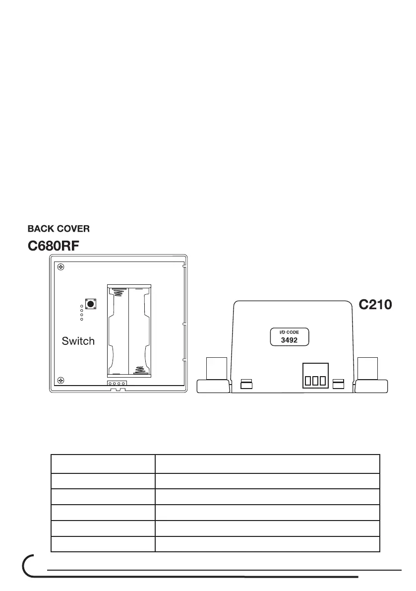
1.5. Press the switch (located next to the LED’s) at the C210 and check that
the red LED is ON. During the time that the RED LED is ON, (A period of 5
minutes),Thecontrollerisreadyforcongurationtoeach 680RF thermostat.
Please note: each C210 controller have unique ID code.
1.6. Open all thermostat back cover and install only one battery at each one.
1.7. Second battery will be installed during the following steps.
1.8. TakeothebackcoveroftheC680RFandInsertthebatteries.After
few seconds, it should appear on the LCD screen of the thermostat, the
“ID code” (4 digits) corresponding to the ID code on the label located at
the side of the C210 unit.
EXAMPLE: The ID code on the label at the side of the C210 controller is 3492.
At the thermostat LCD display will appear the number 34 at the location
of temperature (Large Digits) and at the small digits (at the lower left
side) the number 92.
1.9. Therstthermostat(Masterthermostat)receivedaddressautomatically
corresponding to the C210 - Thermostat 1.
1.10. follow the same to the other C680RF thermostats.
Room No. Damper conected to the C210 Output
1 D1
2 D2
3 D3
4 D4
5 D5