TFP1090
Page 2 of 20
Dry Pipe Valve
The DN100 and DN150, Model DPV-1
Dry Pipe Valves are for vertical installa-
tions (flow going up), and they are rated
for use at a maximum service pressure
of 16 bar (VdS approval range of supply
pressure is 3 to 16 bar). The nominal
pressure loss versus flow is shown in
Graph A, and the valve take-out dimen-
sions are shown in Figure 2.
Flange connections are drilled per ISO
2084 (PN10/16) or ANSI B16.1 (Class
125). The grooved outlet connections,
as applicable, are cut in accordance
with standard groove specifications
for steel pipe. They are suitable for use
with grooved end pipe couplings that
are listed or approved for fire protec-
tion system service.
Threaded port connections per ISO
7-1 readily accept trim arrangements
described in Figures 7 through 14.
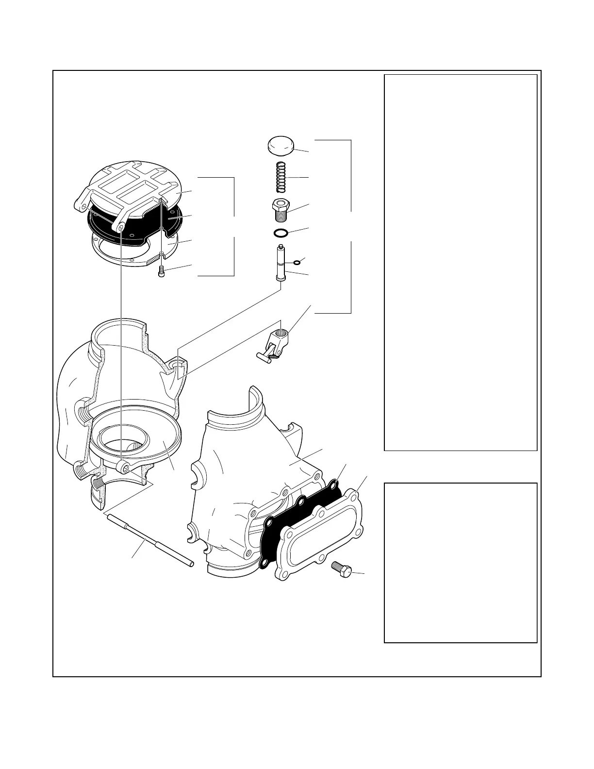
Components of Model DPV-1 Valve
assemblies are shown in Figure 1A for
the DN100 valve and in Figure 1B for
the DN150 valve. The Body and Hand-
hole Cover are ductile iron. The Hand-
hole Cover Gasket is neoprene, and
the Clapper Facing is EPDM. The Air/
Water Seat Ring is brass, the Clapper is
copper, and both the Clapper Retaining
Plate and Latch are bronze. The Hinge
Pin is aluminum bronze, and the fasten-
ers for the Handhole Cover are carbon
steel.
Valve Trim
Valve trim arrangements are shown in
Figures 7 through 14 (Ref. Table A). The
Valve Trim forms a part of the labora-
tory approval of the Model DPV-1 Dry
Pipe Valve and is necessary for the
proper operation of the Model DPV-1
Dry Pipe Valve. Each package of trim
includes the following items:
• Water Supply Pressure Gauge
• System Air Pressure Gauge
• Main Drain Valve
1
2
3
6
7
8
10
11
12
15
17
18
4
5
13
14
16
(a)
(b)
(c)
9
Valve Body NR
NR
NR
See (a)
See (a) or (b)
See (c)
Air and Water
Handhole Cover
Clapper
Clapper Facing
Screw
Clapper Hinge Pin
Reset Knob
Reset Spring
Reset Latch
Seat
Retaining Plate
1/4-20 UNC x 1/2"
Handhole Cover
See (b)Gasket
Hex Head Cap Screw CH
Clapper Facing
See (a)
1/2-13 UNC x 1"
See (c)
Reset Bushing See (c)
Reset Bushing
See (b) or (c)O-Ring
Reset Plunger
See (b) or (c)O-Ring
Reset Plunger See (c)
Dow Corning FS3452
See (b) or (c)Grease, 1.5 g
Flourosilicone
Subassembly See (c)
NO. DESCRIPTION REP. PART
Clapper Assembly
Repair Parts Kit
Reset Plunger Parts Kit
Includes Items 11-18
Includes Items 6-10
Includes Items
4, 7, 14, 15, & 18
92-310-1-405
CH
Socket Head Cap
See (a)
NR: Not Replaceable
CH: Common Hardware
NO. DESCRIPTION P/N
REPLACEMENT PARTS
92-309-2-403
92-309-1-404
See (a)
1
1
1
1
1
1
1
1
1
1
1
1
1
1
1
QTY.
6
7
1
. . . .
. . . . . .
. . . . . . . . . . . .
. . . . . . .
. . .
. . . . . . . . . .
. . . . . . . . . .
. . . .
. . . . .
. . . .
. . . . . . . . . . .
. . . . . . . . . .
. . . . .
. . . . .
. . . . .
. .
. . .
. .
. . .
. . . . .
. .
5
3
4
1
9
11
12
13
14
15, 18
16
17
2
6
7
8
10
CLAPPER
ASSEMBLY
RESET
PLUNGER
PARTS
FIGURE 1A
DN100 MODEL DPV-1 DRY PIPE VALVE
ASSEMBLY
 Loading...


