3.5 WIRING
Loop cabling is connected to base terminals as follows:
L-VE
L1 +VE IN
L2 +VE OUT
R Remote LED Drive
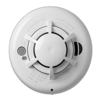
4. MECHANICAL CONSTRUCTION
The major components of the detector are:
• Body Assembly
• Printed Circuit
• Optical Chamber
• Optical Chamber Cover
• Thermistor
• Light Pipe
• Outer Cover
4.1 ASSEMBLY
The body assembly consists of a plastic moulding which has
four embedded detector contacts which align with contacts
in the 5BEx base. The moulding incorporates securing
features to retain the detector in the base.
The PCB is soldered to the body contacts. These contacts
act as a mechanical fixture during assembly and provide
electrical contact between the contacts and the PCB. The
PCB is then potted.
The chamber cover is clipped to the body over the optical
chamber ensuring the thermistor protrudes through the
cover. The light pipe is slotted into the chamber
cover. Finally, the outer cover is clipped to the body.
4.2 TEST AND FINAL ASSEMBLY
The detectors are fully functionally tested and their
sensitivities set in a smoke tunnel to ensure correct
calibration. The sealing ring and labels are then fitted to
complete detector assembly.
5. TECHNICAL SPECIFICATION
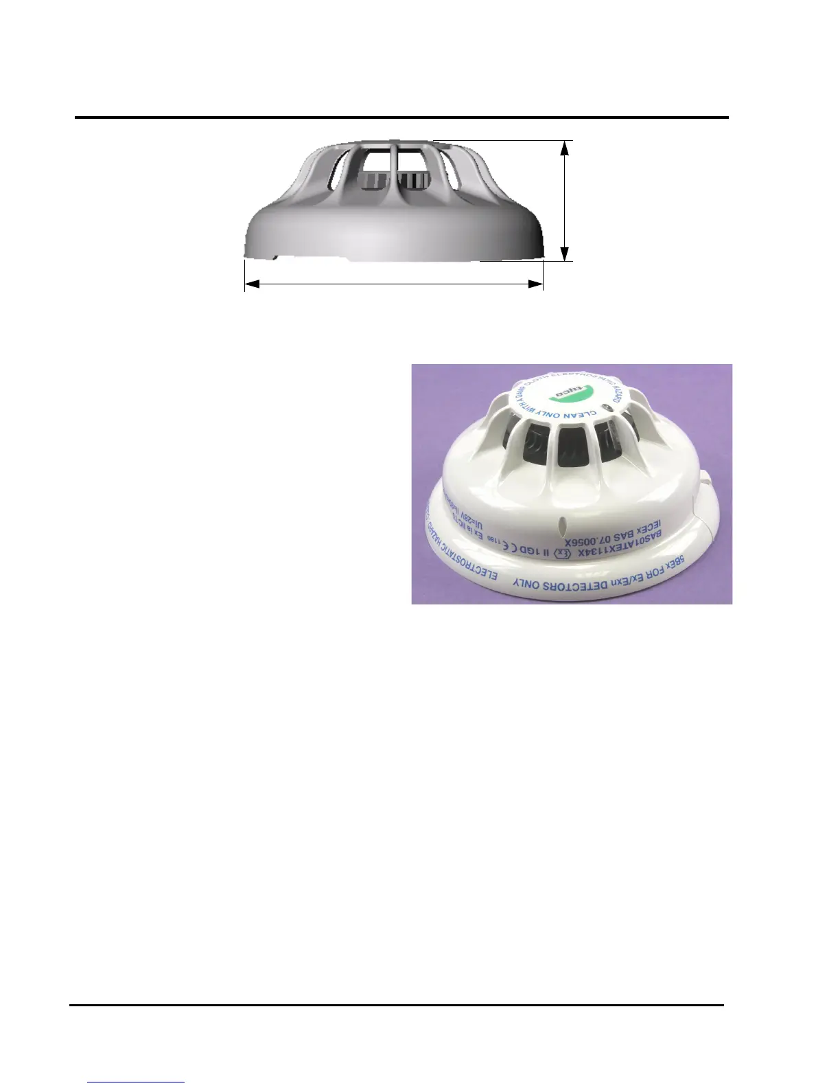
5.1 MECHANICAL
Dimensions
The dimensions of the MR601TEx detector are shown in
Fig. 5.
Materials
Body and cover: FR110 ‘BAYBLEND’
Fire Resistant