T1200
MARINEC-P-A
3 02/14
PAGE 50 of 67
19. Circuit Connection Details
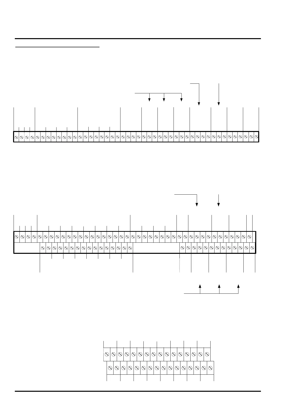
19.1 T1204 (C1626) 4-Zone Panel Termination Details
Figure 19 – C1626 field terminations
Inputs
:
SIL
= Silence alarms
EVAC =
Evacuate
RST
=
Reset
Outputs
:
DIS =
Disablement active
EVAC
= Evacuation active
BUZ Active = Buzzer active
C/+ = Normally Closed or +ve
P = Pole
O/- = Normally Open or -ve
O/+ = Normally Open or +ve
C/- = Normally Closed or -ve
Zone
Outputs
1 2 3 4
Zone Circuits
1 2 3 4
+
-
+
-
+
-
+
-
Alarm Circuits
1 2 3 4
+
-
+
-
+
-
+
-
Aux
DC
24V
0V
C/-
P
O/+
N/O
P
C/+
P
O/-
Fire
Protection
C/+
P
O/-
Reset
N/C
24V
0V
SIL
Inputs Outputs Repeater
EVAC
RST
DIS
EVAC
A B
GND
Class
change
Buz Active
Fault
Routing
[Fault
signal
O/P]
Fire
Routing
[Fire
signal
O/P]
Note: “Evacuate” or “Evac” = Manual Fire Alarm/Muster
19.2 T1216-C and T1232-C (C1627) 16-Zone Motherboard Termination Details
Figure 20 – C1627 field terminations
Inputs
Outputs
Repeater
Inputs:
SIL = Silence alarms
EVAC =
Evacuate
RST =
Reset
Outputs:
DIS = Disablement active
EVAC = Evacuation active
BUZ Active = Buzzer active
Class change
Lower terminal tier
C/+ = Normally Closed or +ve
P = Pole
O/- = Normally Open or -ve
O/+ = Normally Open or +ve
C/- = Normally Closed or -ve
Zone O/Ps
1 2 3 4
Zone Circuits
5 6 7 81 2 3 4
+
-
+
-
+
-
+
-
+
-
+
-
+
-
+
-
Zone Circuits
13 14 15 169 10 11 12
+
-
+
-
+
-
+
-
+
-
+
-
+
-
+
-
Alarm Circuits
1 2 3 4
+
-
+
-
+
-
+
-
Aux
DC
24V
0V
SIL
EVAC
RST
DIS
EVAC
A B
GND
Reset N/C
Buz Active
Upper terminal tier
Fault
Routing
[Fault
signal
O/P]
24 V
0V
O/+
P
C/-
N/O
P
Aux
DC
Fire
Routing
[Fire
signal
O/P]
C/+
P
O/-
Fire
Protection
C/+
P
O/-
Reset
Note: “Evacuate” or “Evac” = Manual Fire Alarm/Muster
19.3 32-Zone Expansion Board Termination Details
Figure 21 – C1632 17-32 zone expansion board field terminations
Zone Circuits
21 22 23 2417 18
19 20
+
-
+
-
+
-
+
-
+
-
+
-
+
-
+
-
Zone Circuits
29 30 31 3225 26 27 28
+
-
+
-
+
-
+
-
+
-
+
-
+
-
+
-
Lower terminal tier
Upper terminal tier
 Loading...

