EQUIPMENT: T1200-C
PUBLICATION: MARINEC-P-A
ISSUE No. & DATE: 3 02/14
© 2014 Thorn Security Ltd PAGE 51 of 67
Registered Company: Thorn Security Ltd. Registered Office: Dunhams Lane Letchworth Garden City Hertfordshire SG6 1BE
19.4 Auxiliary Supply
An auxiliary supply output is available to power
external field equipment from the panel. This
voltage is nominally 27.3Vdc but varies during
mains-failed conditions. See section 21. below for
details of maximum load.
The output is fused using an electronic device, and
fuse activation will be indicated as Fuse Failed on
the panel display. The fuse can be reset after
removal of the fault by operating the Reset button
on the display.
The auxiliary supply terminals are labelled Aux DC
0V and 24V. Although two sets of terminals are
provided, they are both protected by the same fuse
circuit and therefore the total load across both sets
of terminals must not exceed the rated value.
Note: If equipment draws current from the
auxiliary supply during the mains-failed
condition this must be included in the battery
capacity calculations.
19.5 Fire Protection, Fire Output and
Fault Output Signal Outputs
These outputs are factory set to the fault-monitored,
powered mode of operation but can be configured
at site to volt-free relay outputs [See 17.23 above].
Connection details for both types of configuration
are provided in Figure 24.
19.6 Use of Auxiliary Inputs
Auxiliary inputs are provided to allow remote
operation of the following functions:
Auxiliary Input: Type of activating switch:
Remote Manual Fire
Alarm/Muster.
Two-position latching
To activate an input, 0Vdc should be connected to
the input circuit via a normally open contact
arranged to close. [See Figure 22 – Auxiliary I/P
connection detail]
Figure 22 – Auxiliary I/P connection detail
Sil, Evac, Reset
or Class Change
Aux 0VDC
External normally open
switch or relay contact,
closing to activate I/P
Field WiringPanel Wiring
Note: “Evacuate” or “Evac” = Manual Fire
Alarm/Muster
Note: To prevent unauthorised operation of the
system, any manually operated auxiliary
input must be operated by a key-switch.
The key to the switch should be held with
the panel’s access control key.
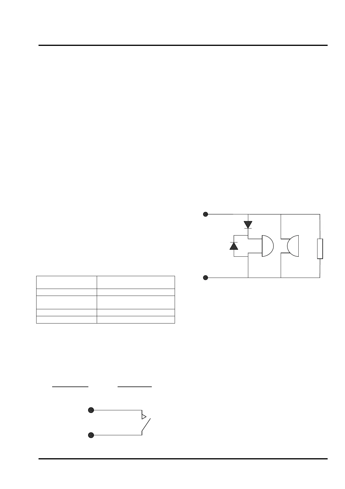
19.7 Sounder Circuits
The T1204 panel has 4 sounder circuits, each rated
at 0.5A. The T1216-C and T1232-C panels have 4
sounder circuits each rated at 1A. The circuits are
reverse polarity monitored for open and short circuit
faults. All connected field devices must be polarised
to allow correct fault monitoring. To prevent
damage to the control panel, any solenoid devices
such as bells must also have a suppression diode
fitted as shown in Figure 23 – Alarm circuit
configuration.
The circuit must be terminated with a 3K9 end-of-
line resistor.
Figure 23 – Alarm circuit configuration
Polarising
diode
[1
N4002S
]
Suppression
diode
[1
N4002S
]
Bell
Electronic
sounder
3K9
End of
line
resistor
Alarm +
Alarm -
The voltage drop on each alarm circuit should be
calculated to ensure that the minimum voltage at
the end of each circuit exceeds the minimum
required by each sounding device.
The voltage at the end of the circuit is given by:
V
Amin
= V
Omin
- (I
A
x 2 x L x R
C
)
V
Amin
= Minimum Alarm Voltage
V
Omin
= Minimum Output Voltage**
I
A
= Alarm Current in Amps
L = Alarm Circuit Length in metres
R
C
= Cable resistance (Ohms per metre)
** Min O/P voltages:
T1204 = 19.2V
T1216-C = 19.2V
T1232-C = 18.4V
The resistance per metre is as follows:
1.5mm
2
- 0.015Ω per metre per core
2.5mm
2
- 0.009Ω per metre per core
 Loading...

