STEP 1
PROCEDURE:
REMOVE CONTENTS FROM BOX. VERIFY ALL PARTS ARE PRESENT.
READ INSTRUCTIONS CAREFULLY BEFORE STARTING INSTALLATION.
ASSISTANCE IS RECOMMENDED.
Driver/Left side Installation Pictured
Driver/Left side Installation Pictured
Start the installation under the driver/left side of the vehicle.
Locate the plastic plug along the bottom edge of the body (Fig
1). Directly above each threaded hole is a top mounting location
on the side of the body panel. Hold Mounting Bracket up in place
to help determine the mounting holes to use along the body.
NOTE: Remove excess sealant or paint from area around
threads. Thread an 8mm Hex Bolt into the threaded inserts to
clear paint from threads as necessary.
TYGER LanderX
STEP 2
Select (1) Driver/Left Side Mounting Bracket (Fig 2). Attach
the Bracket to the (2) threaded holes with the included (2) 8mm
x 30mm Hex Bolts, (2) 8mm Lock Washers and (2) 8mm Flat
Washers (Figs 2 & 3). DO NOT fully tighten hardware.
2/5
(Fig 1) Remove plastic plugs to uncover threaded
inserts. Driver/left front location pictured
Remove plugs (arrows)
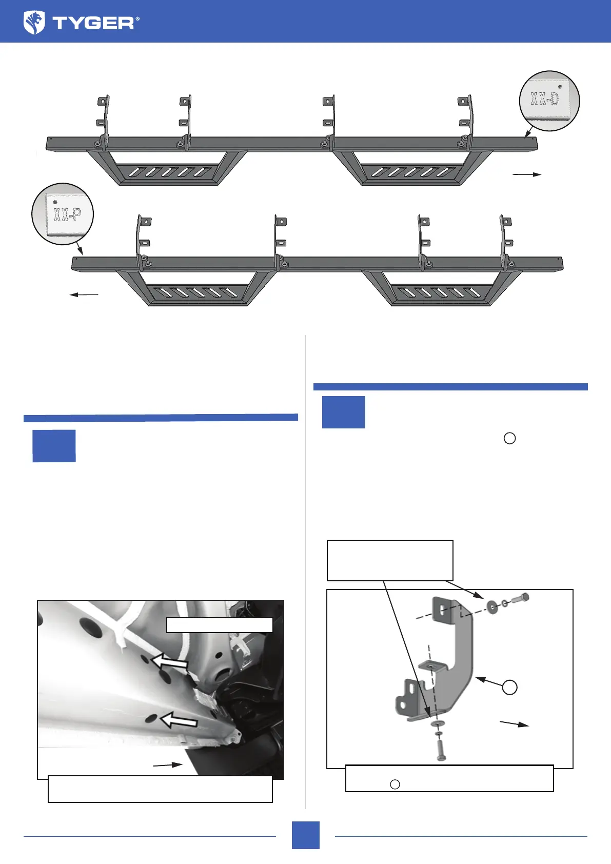
ATTENTION: Refer to the D or P labelling on the tubes to determine the Driver or Passenger side steps.
Bottom View
Passenger/Right LanderX
Driver/Left LanderX
Front
Front
XX-P
XX-D
Front
(Fig 2) Attach the Driver/Left Mounting
Brackets to the threaded holes in the oor
Front
(2) 8mm x 30mm Hex Bolts
(2) 8mm Lock Washers
(2) 8mm Flat Washers
A
A
A