12
37
35
36
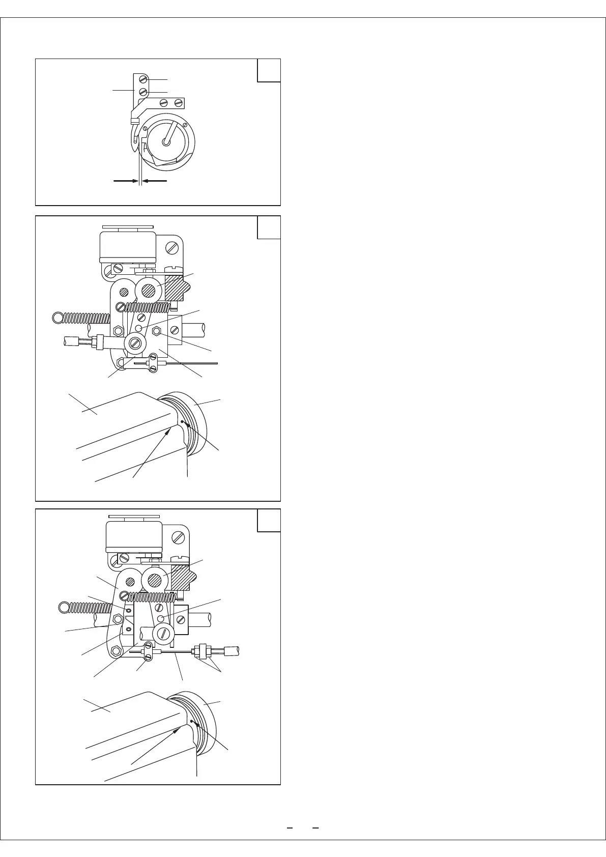
5.4.2 Adjusting the clearance between the movable knife
and the rotating hook position block. (Fig.35)
a. Turn the balance wheel to lower the needle bar to its
lowest position.
b. Press down the trimming driven crank and turn the
balance wheel, so that the movable knife can go forward
as far as it can go.
c. Turn the inner rotating hook by hand to adjust the
clearance between the movable knife and bobbin case
position block to 0.2mm.
(Loosen the screw A, B before adjusting.)
5.5 Adjusting the trimming cam (Fig.36)
a. Turn the balance wheel to lower the needle bar to its
lowest position.
b. Maintain the position of needle bar, press down the
trimming driven crank, so that the trimming roller can
get into the trimming cam groove.
c. Turn the balance wheel, adjust the trimming cam to
make the white mark on the balance wheel align with the
position mark line on the arm, then the movable knife
starts working.
(Loosen the two set screws A on the trimming cam before
adjusting.)
5.6 Adjusting the thread releasing assembly (Fig.37)
a. Turn the balance wheel to lower the needle bar to its
lowest position.
b. Maintain the position of needle bar, press down the
trimming driven crank, so that the trimming roller can
get into the trimming cam groove.
c. Turn the balance wheel, adjust the trimming cam to
make the white mark on the balance wheel align with the
position mark line on the arm, then the Thread tension
disc is closed.
(Loosen the screws A on the threading releasing cam
before adjusting.)
Adjusting the open range of the thread tension disc by the
thread releasing roller B and thread releasing cam. When
adjusting, loosen the adjusting screw C, and shrink the
drawing rope.
When carrying out the fine adjustment, loosen the screw
cap D, move the outside cover of the drawing rope
rightward to enlarge the open range of the thread tension
disc.
Screw A
Screw B
Movable knife
Bobbin case
About 0.2mm
Trimming driven crank
Trimming roller
Screw A
Trimming cam
Balance wheel
Red mark
Position mark
Arm
Cam groove
Balance wheel
Red mark
Position mark
Arm
Screw A
Screw C
Thread releasing
vibrating lever
Thread releasing
roller B
Thread releasing
cam
Trimming cam
Trimming driven crank
Trimming roller
Drawing rope
Screw cap D