1
2
1
A
B
★.Optional gauge size:3.2、4、4.8、8、9.5、12.7、
16、19、25.4mm
2. Main specifications
Model
Specifications
Medium and heavy duty
1800spm
9mm
8mm by hand, 13mm by knee
36mm
Large vertical hook with auto-lubrication
DP×17 Nm125-180
6.4mm (standard)
Auto lubrication (partial of manually oiling)
Servo motor 550W
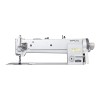
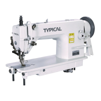
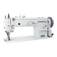
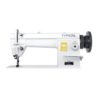
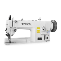
The models adopt double (single) needle and two (single)
vertical hooks with auto lubrication for thread looping,
sliding lever for thread take up to form two lines of
lockstitch seam. The upper shaft and lower shaft are
supported by ball bearing and driven by teeth-type
synchronic belt; plunge oil pump lubrication system.
They adopt the compound feed mechanism of feed dog,
needle bar and presser foot, even if for long stitch length
and long material. This series can deal with them freely.
This series adopts numerical computerized control
sy st em , wh ic h is des ig ne d wi th a u t o - t ri mm in g,
a u t o - s e t t i n g s t i t i c h l e n g t h , a u t o - b a c k t a c k i n g ,
auto-presser foot lifter, etc. It is also designed with the
electrical servo motor.
This series is widely used in the factories of suitcase,
tent, cushion, leather, goods, apparel, mat, etc.
.
.
1. Brief Introduction
Application
Max.sewing speed
Max.stitch length
Presser foot lift volume
Needle bar stroke
Rotating hook
Needle
Needle gauge
Lubrication
Motor
3.1 Installation
3.1.1 Location of the machine
To ensure a smooth running, the machine should be located
on a rigid and flat floor. The insert of rubber mat between
machine stand and floor is recommended for further reducing
the running noise and vibration.
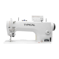
3.1.2 Installing the oil reservoir (Fig.1)
Put the oil reservoir into the table cutout, and place the four
cushions on the four corners of the cutout, then set the
cushions and oil reservoir in the table.
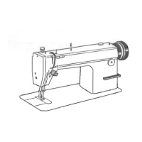
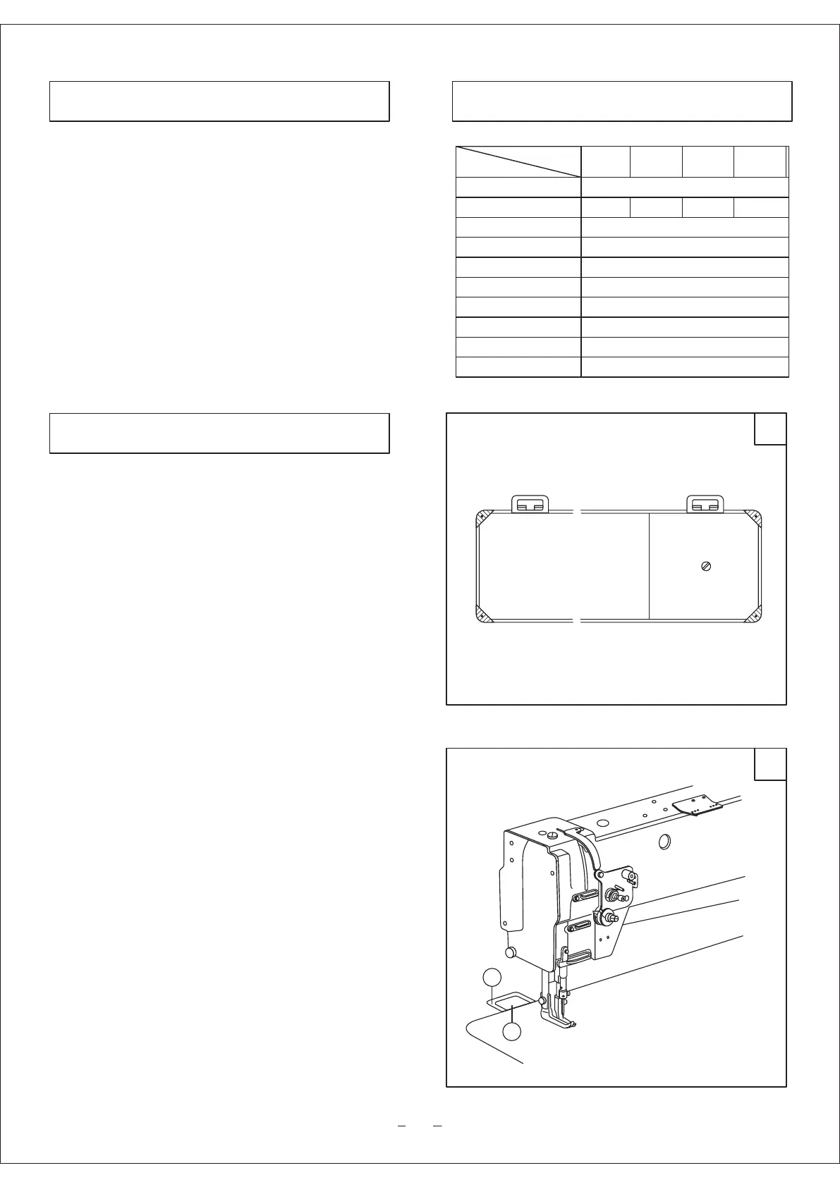
3.1.3 Installing the machine head (Fig.2)
Set the hinge A onto the hinge socket B on the table, then turn
the machine head freely until it is seated on the frame of table
cutout
3. Installation and preparation
GC20606
L18-D2T
/HL18-D2T
GC20606
-1L18-D2T
/-1HL18-D2T
GC20606
-D2
GC20606
-1-D2
1800spm1200spm 1200spm