C
B
A
3
6
5
2
A
4
A
B
C
A
B
C
b
a
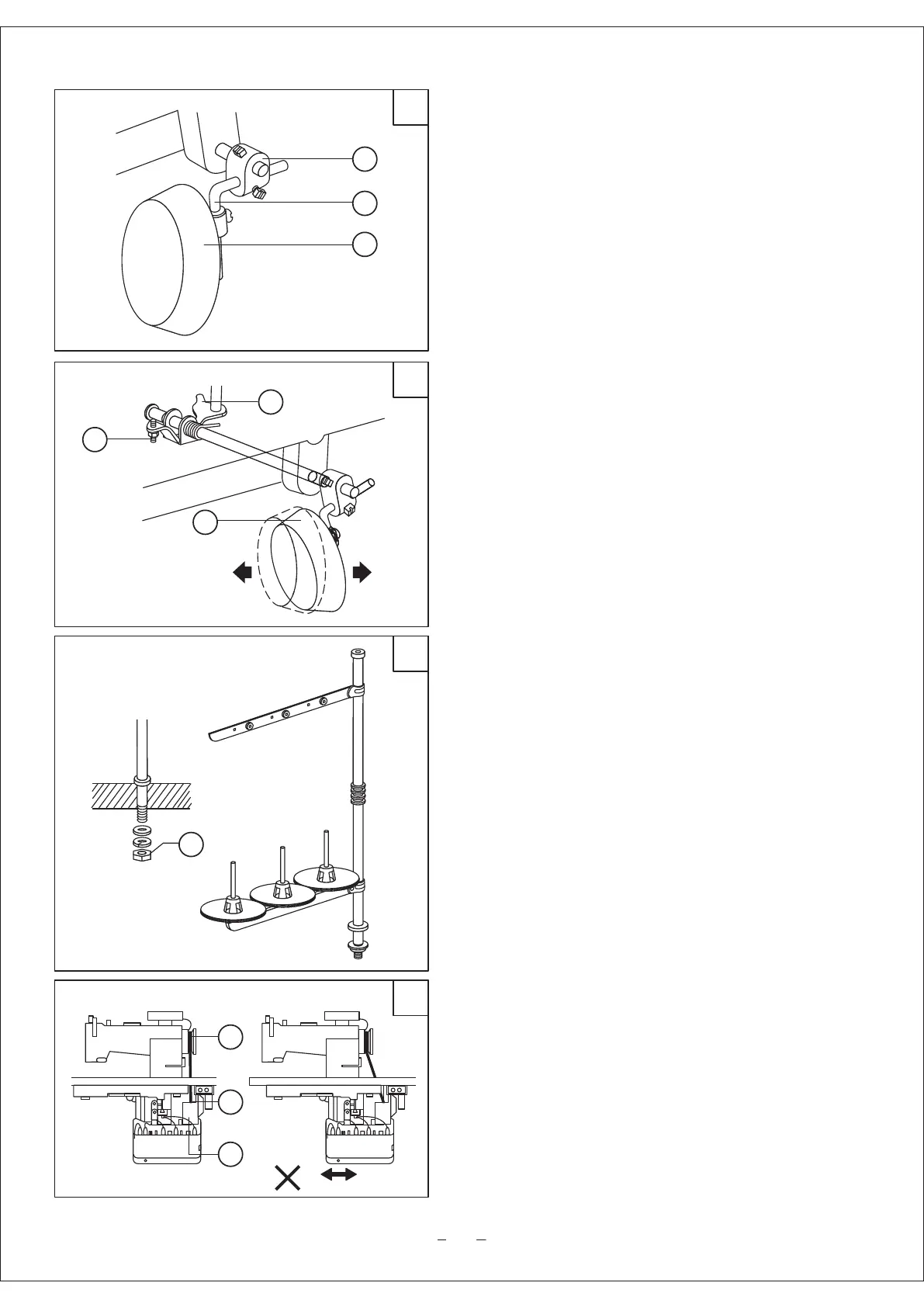
3.1.4 Knee control presser foot lifter installation (Fig.3)
a. Installation
Install the Connector A, Bell crank B, Bell C in the order
shown in Fig.3.
B. Adjustment (Fig.4)
1. When the presser foot is at its lowest position, keep
the crank in the position shown by b in the figure; turn
the knee control stop adjusting screw C to touch with the
oil reservoir, and tighten the nut of screw C.
2. When it is operated by knee, the presser foot lift
volume is controled by screw B. Turn the presser foot
down, make the bell in the position shown in the figure,
lift the presser foot to 13mm, adjust the screw B to touch
with the oil reservoir, then tighten the nut of screw B.
3.1.5 Installing the thread spool stand (Fig.5)
Locate the thread spool stand at the right front of the
table, note that spool rest may not obstruct when
machine head is turned backward, then tighten the nut A.
3.1.6 Installing the motor (Fig.6)
Align the machine balance wheel belt groove A with
motor pulley belt groove B by moving the motor C
leftward and rightward. Be sure the belt is not touch
with table.