3.
INSTALLATION
7
(15)~
"-----(16)
(14)
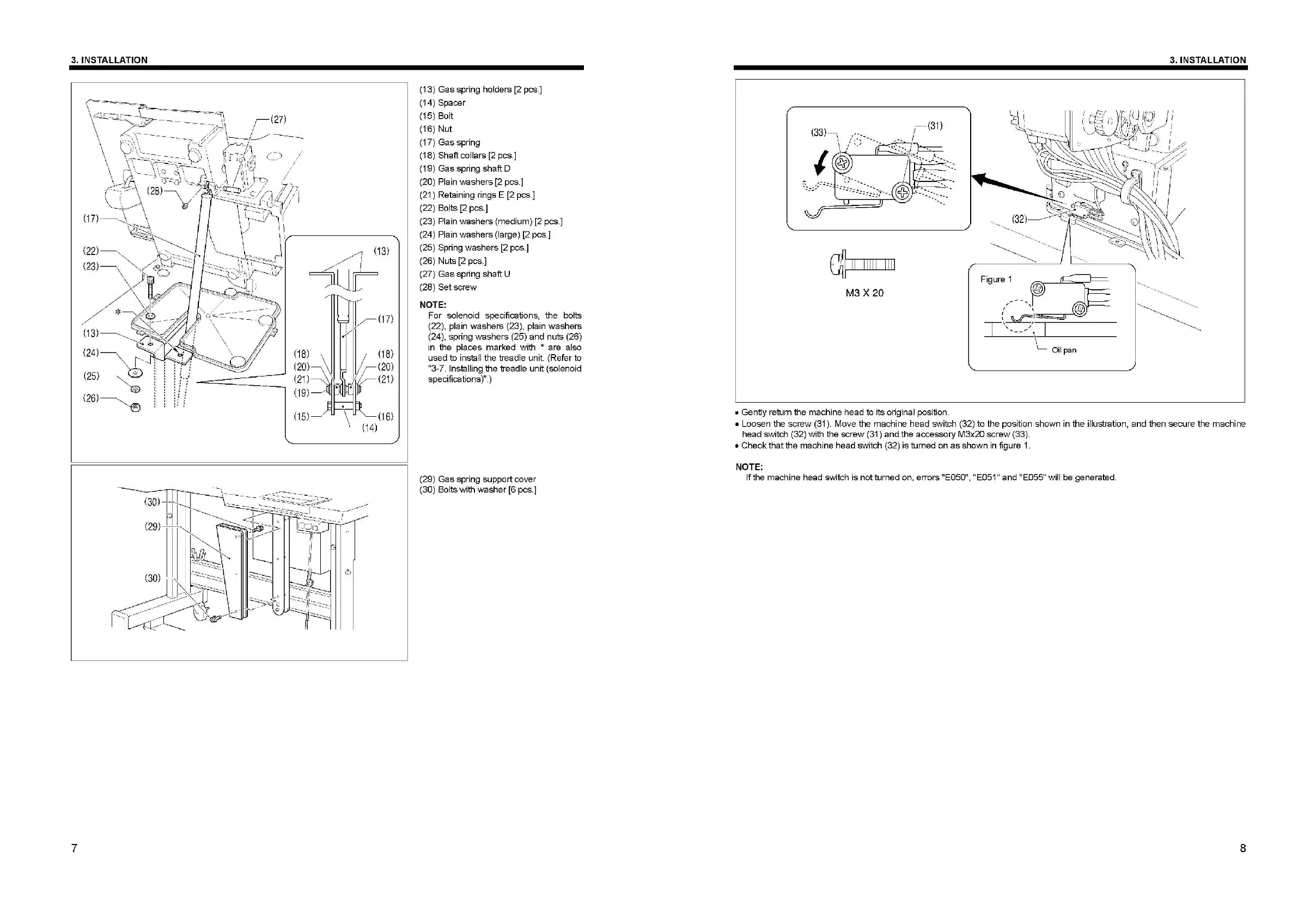
(13)
Ga
s spring
ho
lders [2 pcs
.]
(14) Spacer
(1
5)
Bo
lt
(1
6)
Nut
(17) Gas spring
(1
8)
Shaft
co
llars
[2
pcs.]
(1
9)
Gas spring shaft D
(
20
) Plain washers [2 pcs
.]
(
21
) Retaining rings E [2 pcs
.]
(2
2)
Bo
lts [2 p
cs
.]
(23) Plain
wa
shers (med
iu
m) [2 pcs
.]
(
24
) Plain washers (large) [2 pcs.]
(25)
Sp
ring washers [2 pcs.]
(2
6)
Nuts [2 pcs
.]
(27)
Ga
s spring shaft U
(
28
) Setscrew
NOTE:
For solenoid specifica
ti
ons, the bolts
(22). plain washers (23), plain washers
(
24
), spring washers (25) and nuts (26)
in
th
e p
la
ces marked with * are also
used to inslall the treadle
un
i
t.
(Refer
to
"3-7.
ln
stalling the treadle unit (solenoid
specifications )
".
)
(29) Gas spring sup
po
rt cover
(
30
)
Bo
l
ts
with washer [6 pcs.]
(
33
)- ,
' I
c{]
II
111
11
111 1
M3X20
• Gently return the m
ac
hine head to i
ts
original positi
on
.
3.
INSTALLATION
Figure 1
;
I I
T
!·
-:5
~:
==--rr--'
~
I,
L_
Oil
pan
• Loosen the
sc
rew (31 ). Move the machine head switch (
32
) to the position shown in the i
llu
stration, and then
sec
u
re
the m
ac
hine
head
sw
itch (32) wi
th
the screw (31) and the accesso
ry
M3x20 screw (33).
• Checkth
at
the machine head
sw
itch (32) is tumed on
as
sh
ow
n in fig
ur
e 1.
NOTE:
lft
he
machine head switch is notturned on. errors "E050", "E051" and "E055" w
il
l be generated.
8
 Loading...