LEA-5, NEO-5, TIM-5H - Hardware Integration Manual
GPS.G5-MS5-09027-A2 Released Design-in
Page 27 of 68
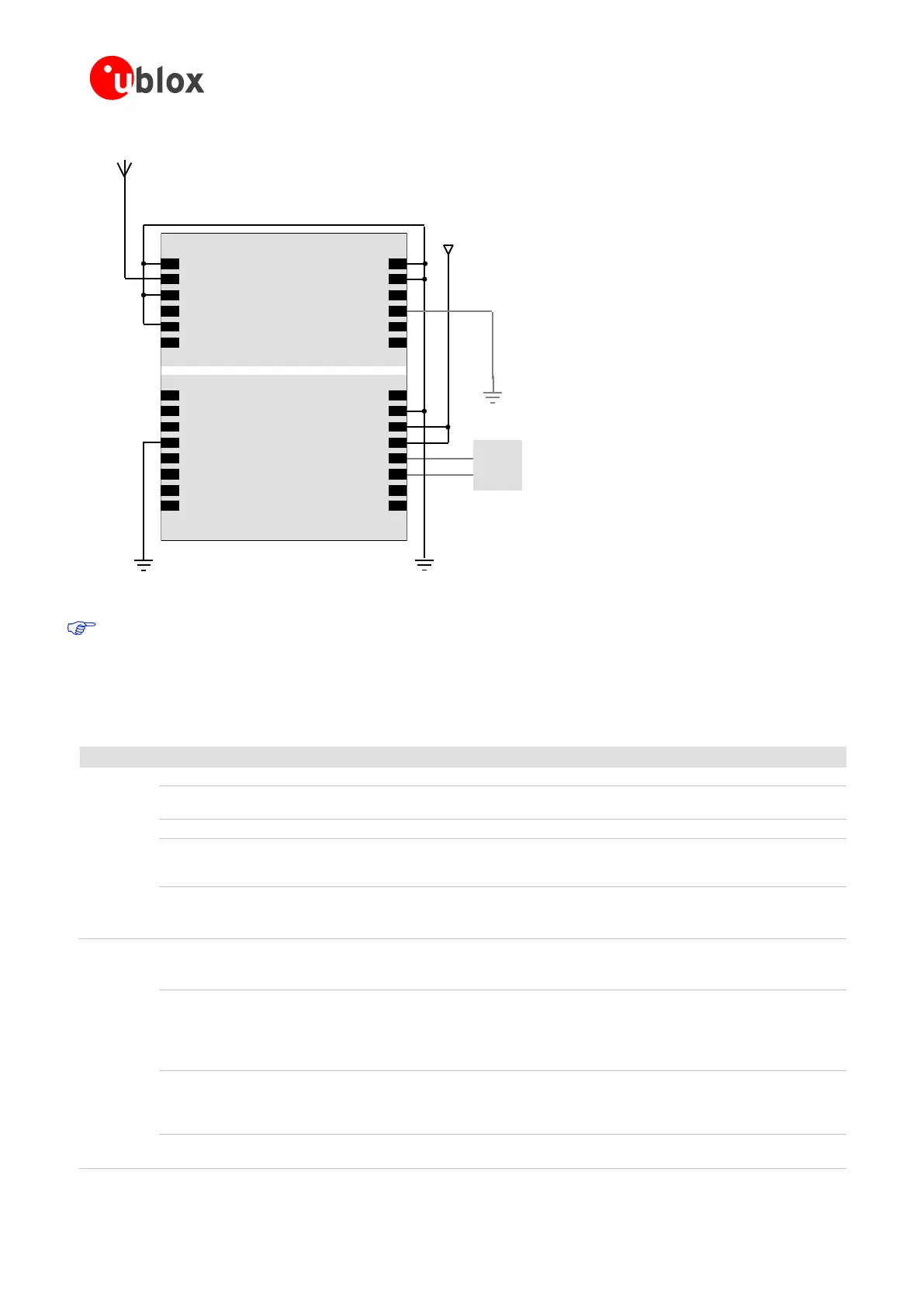
Passive Antenna
Vcc
Micro
Processor
(serial)
1
SDA2
SCL2
TxD1
RxD1
NC/VDDIO
VCC
GND
VCC_OUT
CFG_COM1/MISO
/Reserved
RESET_N
V_BCKP
Reserved
GND
GND
RF_IN
VCC_RF
V_ANT/NC
NC/MOSI/CFG_COM0
NC/SS_N/Reserved
NC/SCK/CFG_GPS0
VDDUSB
USB_DM
USB_DP
EXTINT0
TIMEPULSE
GND
GND
AADET_N/SCS1_N
/Reserved
2
3
4
5
6
7
8
9
10
11
12
13
14
28
27
26
25
24
23
22
21
20
19
18
17
16
15
LEA-5
Top View
Figure 15: Passive antenna design for LEA-5 receivers not using USB port and not using backup battery
For passive antenna designs use an LNA to increase sensitivity up to 2dB.
2.2.2 Pin description for antenna designs (LEA-5H/5S/5A/5T)
Provide clean and stable supply.
Assure a good GND connection to all GND pins of the module,
preferably with a large ground.
Connected to VCC. Leave open if not used.
It‖s recommended to connect a backup battery to V_BCKP in order
to enable Warm and Hot Start features on the receivers. Otherwise
connect to GND (or VCC).
To use the USB interface connect this pin to 3.0 – 3.6V derived from
VBUS.
If no USB serial port used connect to GND.
GPS/GALILEO
signal input
from antenna
Use a controlled impedance transmission line of 50 Ohm to connect
to RF_IN.
Don‖t supply DC through this pin. Use V_ANT pin to supply power.
Output Voltage
RF section
Can be used to power an external active antenna (VCC_RF
connected to V_ANT with 10R). The max power consumption of
the Antenna must not exceed the datasheet specification of the
module.
Leave open if not used.
Connect to GND (or leave open) if Passive Antenna is used. If an
active Antenna is used, add a 10R resistor in front of V_ANT input
to the Antenna Bias Voltage or VCC_RF for short circuit protection
use the antenna supervisor circuitry.
Input pin for optional antenna supervisor circuitry. Leave open if not
used.

 Loading...

