Figure 37: In-band jamming sources
Measures against in-band jamming include:
• Maintaining a good grounding concept in the design
• Shielding
• Layout optimisation
• Filtering
• Placement of the GPS antenna
• Adding a CDMA, GSM, WCDMA bandpass filter before handset antenna
3.3.8.4 Out-band jamming
Out-band jamming is caused by signal f
requencies that are different from the GPS carrier (see Figure 38). The main
sources are wireless communication systems such as GSM, CDMA, WCDMA, WiFi, BT, etc..
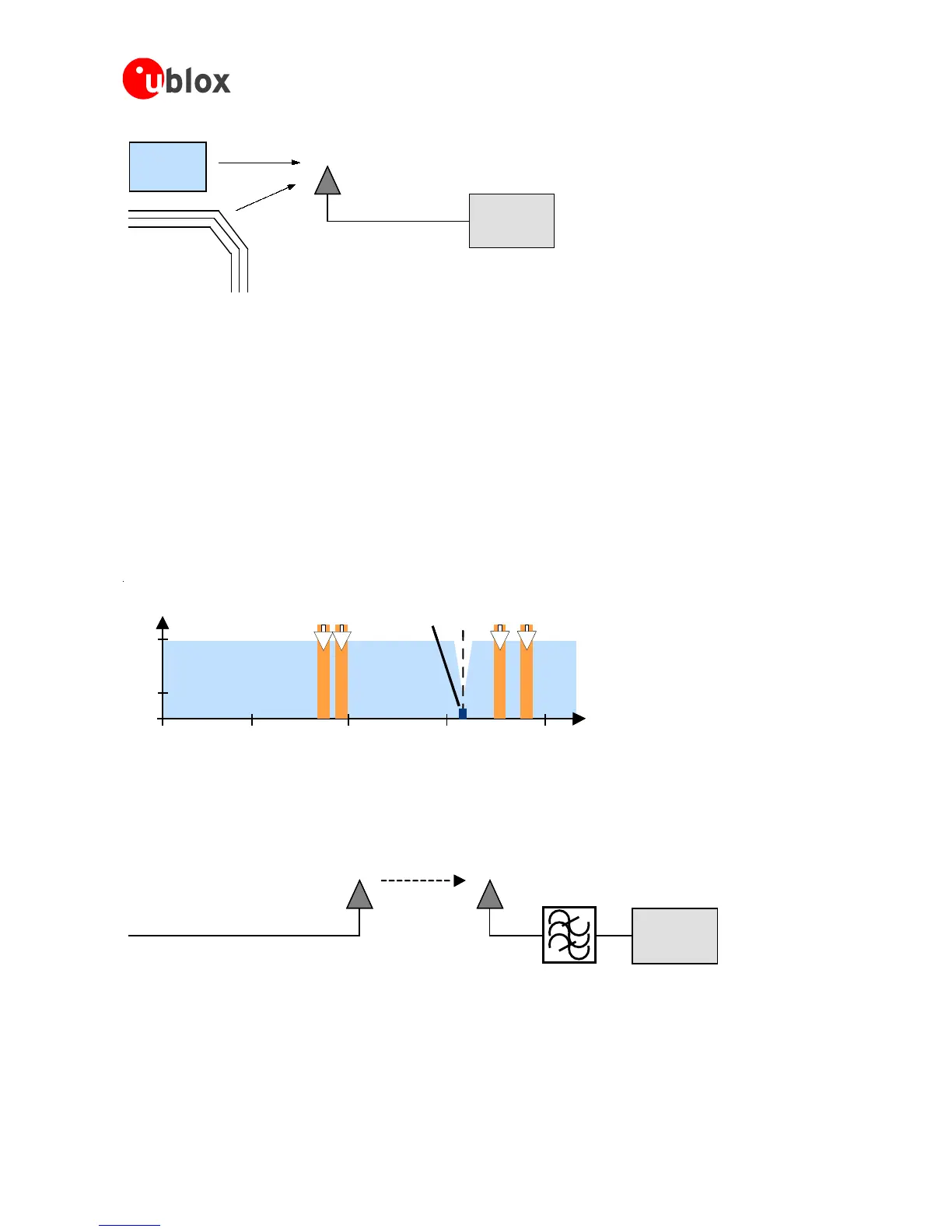
Figure 38: Out-band jamming signals
Measures against out-band jamming include maintaining a good grounding concept in the design and adding a
SAW or bandpass ceramic filter (as recommend in Section 3.3.6) into the antenna input line to the GPS receiver
(see Figure 39).

 Loading...
