000000 NEO-M8L - Hardware integration manual
UBX-16010549 - R08 Hardware description Page 9 of 28
C1-Public
message can also be used to provide the direction of motion (SW interface). For more information,
see the
u-blox 8 / u-blox M8 Receiver Description Including Protocol Specification
[4].
☞ Do not exceed the maximum voltage of 3.6 V at the input when using the HW interface. When
using a SW interface this pin is not used and can be left open.
☞ No forward or reverse input will cause incorrect operation.
1.5.4 D_SEL: Interface select
The D_SEL pin selects the available interfaces. SPI cannot be used simultaneously with the
UART/DDC. If open, UART and DDC are available. If pulled low, the SPI interface is available.
1.5.5 LNA_EN: LNA enable
In power save mode, the system can turn on/off an optional external LNA using the LNA_EN signal in
order to optimize power consumption.
1.5.6 TIMEPULSE
A configurable time pulse signal is available with the NEO-M8L modules. It generates pulse trains
synchronized with GPS or UTC time grid with intervals configurable over a wide frequency range. For
more information, see the u-blox 8 / u-blox M8 Receiver Description Including Protocol Specification
[4].
☞ The NEO-M8L time-pulse output is configured using messages for “TIMEPULSE2”.
☞ The time-pulse output must not be held LOW during start-up.
1.6 Electromagnetic interference on I/O lines
Any I/O signal line with a length greater than approximately 3 mm can act as an antenna and may pick
up arbitrary RF signals transferring them as noise into the GNSS receiver. This specifically applies to
unshielded lines, in which the corresponding GND layer is remote or missing entirely, and lines close
to the edges of the printed circuit board.
If, for example, a cellular signal radiates into an unshielded high-impedance line, it is possible to
generate noise in the order of volts and not only distort receiver operation but also damage it
permanently.
On the other hand, noise generated at the I/O pins will emit from unshielded I/O lines. Receiver
performance may be degraded when this noise is coupled into the GNSS antenna (see Figure 16).
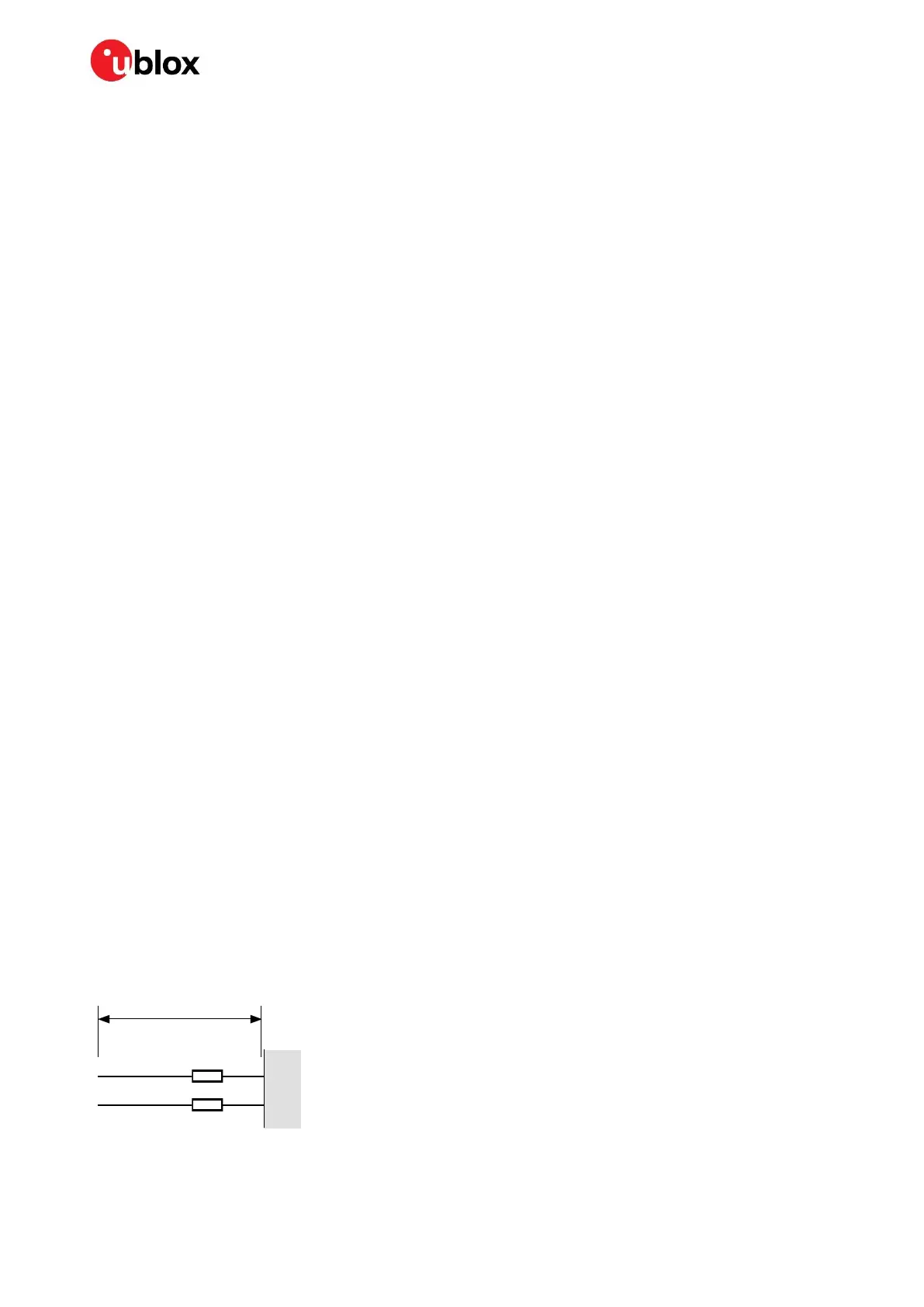
To avoid interference by improperly shielded lines, it is recommended to use resistors (for example,
R>20 ), ferrite beads (for example, BLM15HD102SN1) or inductors (for example, LQG15HS47NJ02)
on the I/O lines in series. Choose these components carefully because they also affect the signal rise
times.
Figure 3 shows an example of EMI protection measures on the RX/TX line using a ferrite bead.
Figure 3: EMI precautions
More information is available in section 4.3.
TX
RX
GNSS
Receiver
FB
FB
BLM 15HD102SN1
>10mm

 Loading...


