000000 NEO-M8L - Hardware integration manual
UBX-16010549 - R08 Design Page 12 of 28
C1-Public
2.4 Antenna
2.4.1 Antenna design with passive antenna
A design using a passive antenna requires more attention to the layout of the RF section. Typically, a
passive antenna is located near electronic components; therefore, care should be taken to reduce
electrical noise that may interfere with the antenna performance. Passive antennas do not require a
DC bias voltage and can be directly connected to the RF input pin RF_IN. Sometimes, they may also
need a passive matching network to match the impedance to 50 .
Figure 6 shows a minimal setup for a design with a good GNSS patch antenna. For exact pin
orientation, see the Appendix and the corresponding product Data sheet [1], [2], or [3] in the Related
documents section.
Figure 6: Module design with passive antenna
☞ Use an antenna that has sufficient bandwidth to receive all GNSS constellations. For more
information, see and the GPS Antenna Application Note [6].
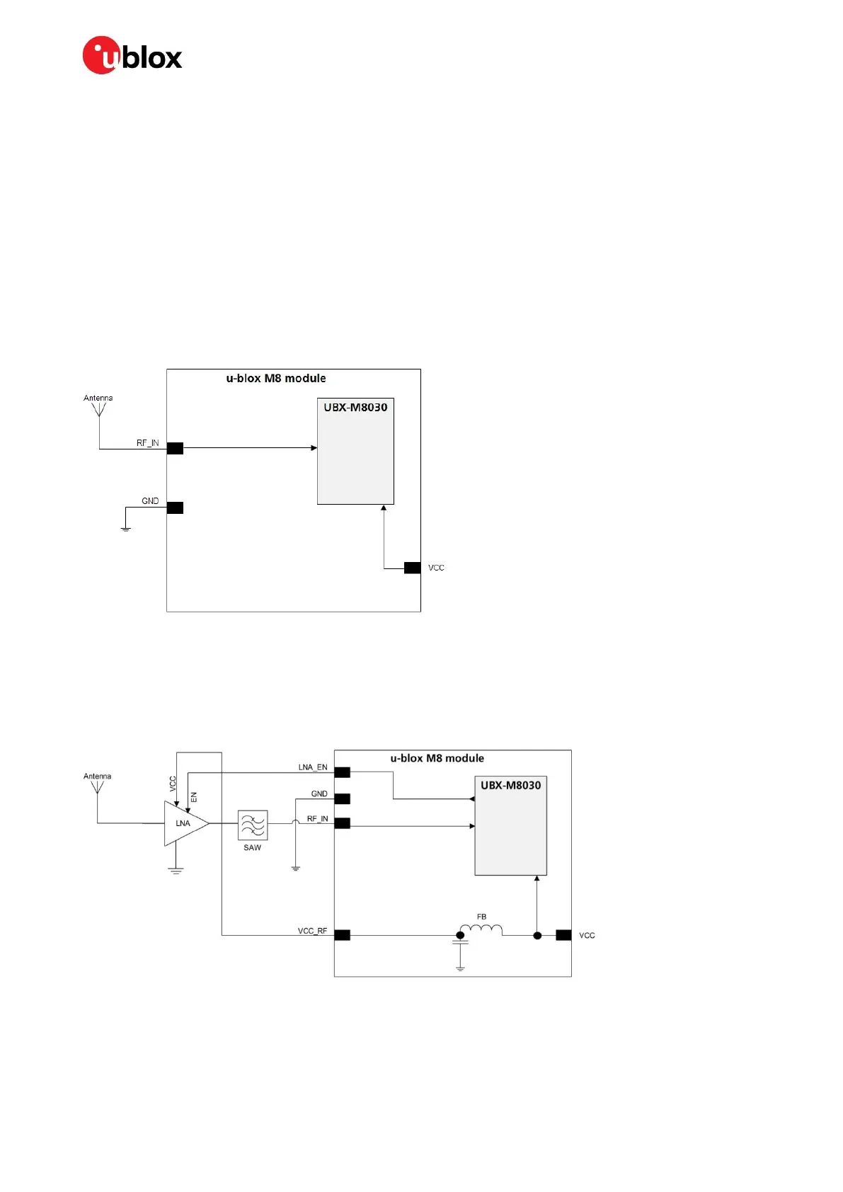
Figure 7 shows a design using an external LNA and SAW to increase the sensitivity for best
performance with passive antenna.
Figure 7: Module design with passive antenna and an external LNA and SAW
The LNA_EN pin (LNA enable) can be used to turn an optional external LNA on and off.
The VCC_RF output can be used to supply the LNA with a filtered supply voltage.
☞ A standard GNSS LNA has enough bandwidth to amplify GPS/GLONASS/BeiDou/Galileo signals.

 Loading...


