SARA-G3 series - System Integration Manual
UBX-13000995 - R06 Objective Specification Design-in
Page 116 of 218
Ensure solid metal connection of the adjacent metal layer on the PCB stack-up to main ground layer,
providing enough on the adjacent metal layer, as described in Figure 40Figure 40
Route RF transmission line far from any noise source (as switching supplies and digital lines) and
from any sensitive circuit (as analog audio lines)
Avoid stubs on the transmission line
Avoid signal routing in parallel to transmission line or crossing the transmission line on buried metal
layer
Do not route microstrip line below discrete component or other mechanics placed on top layer
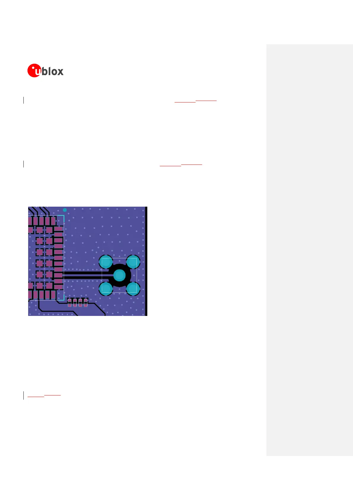
An example of proper RF circuit design is reported in the Figure 40Figure 40. In this case, the antenna
detection circuit is not implemented: the ANT pin is directly connected to an SMA connector by means of
a proper 50 transmission line, designed with proper layout.
If the antenna detection function is required by the application, follow the guidelines for circuit and layout
implementation reported in section 2.3.2.
SARA-G3 series
SMA
connector
Figure 40: Suggested circuit and layout for antenna RF circuit on application board, if antenna detection is not required
Guidelines for RF termination design
The RF termination must provide a characteristic impedance of 50 as well as the RF transmission line
up to the RF termination itself, to match the characteristic impedance of the ANT pin of SARA-G3
modules.
However, real antennas have no perfect 50 load on all the supported frequency bands. Therefore, to
reduce as much as possible performance degradation due to antenna mismatch, the RF termination must
provide optimal return loss (or V.S.W.R.) figure over all the operating frequency bands, as summarized in
Table 8Table 8.
 Loading...