SARA-G3 series - System Integration Manual
UBX-13000995 - R06 Objective Specification Design-in
Page 124 of 218
SARA-G3 series
41
VSIM
39
SIM_IO
38
SIM_CLK
40
SIM_RST
4
V_INT
42
SIM_DET
SIM CHIP
SIM Chip
Bottom View
(contacts side)
C1
VPP (C6)
VCC (C1)
IO (C7)
CLK (C3)
RST (C2)
GND (C5)
C2 C3 C5
U1
C4
2
8
3
6
7
1
C1 C5
C2 C6
C3 C7
C4 C8
8
7
6
5
1
2
3
4
TP
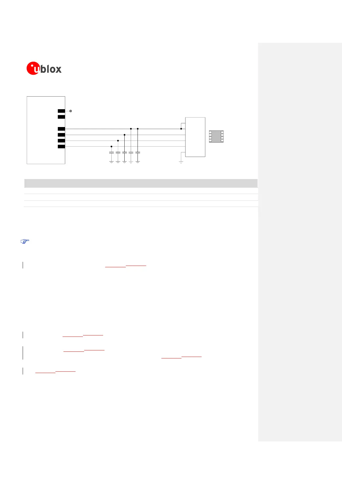
Figure 44: Application circuit for the connection to a single solderable SIM chip, with SIM detection not implemented
Part Number - Manufacturer
47 pF Capacitor Ceramic C0G 0402 5% 50 V
GRM1555C1H470JA01 - Murata
100 nF Capacitor Ceramic X7R 0402 10% 16 V
GRM155R71C104KA01 - Murata
SIM chip (M2M UICC Form Factor)
Table 24: Example of components for the connection to a single solderable SIM chip, with SIM detection not implemented
Guidelines for single SIM card connection with detection
SIM card detection is not supported by SARA-G300-00S and SARA-G310-00S modules.
A removable SIM card placed in a SIM card holder must be connected to the SIM card interface of
SARA-G3 modules as described in Figure 45Figure 45, where the optional SIM card detection feature is
implemented.
Follow these guidelines connecting the module to a SIM connector implementing SIM presence detection:
Connect the UICC / SIM contacts C1 (VCC) and C6 (VPP) to the VSIM pin of the module
Connect the UICC / SIM contact C7 (I/O) to the SIM_IO pin of the module
Connect the UICC / SIM contact C3 (CLK) to the SIM_CLK pin of the module
Connect the UICC / SIM contact C2 (RST) to the SIM_RST pin of the module
Connect the UICC / SIM contact C5 (GND) to ground
Connect one pin of the mechanical switch integrated in the SIM connector (e.g. the SW2 pin as
described in Figure 45Figure 45) to the SIM_DET input pin of the module
Connect the other pin of the mechanical switch integrated in the SIM connector (e.g. the SW1 pin as
described in Figure 45Figure 45) to the V_INT 1.8 V supply output of the module by means of a
strong (e.g. 1 k) pull-up resistor, as the R1 resistor in Figure 45Figure 45
Provide a weak (e.g. 470 k) pull-down resistor at the SIM detection line, as the R2 resistor in
Figure 45Figure 45
Provide a 100 nF bypass capacitor (e.g. Murata GRM155R71C104K) at the SIM supply line
(VSIM), close to the relevant pad of the SIM connector, to prevent digital noise
 Loading...