SARA-G3 series - System Integration Manual
UBX-13000995 - R06 Objective Specification Design-in
Page 141 of 218
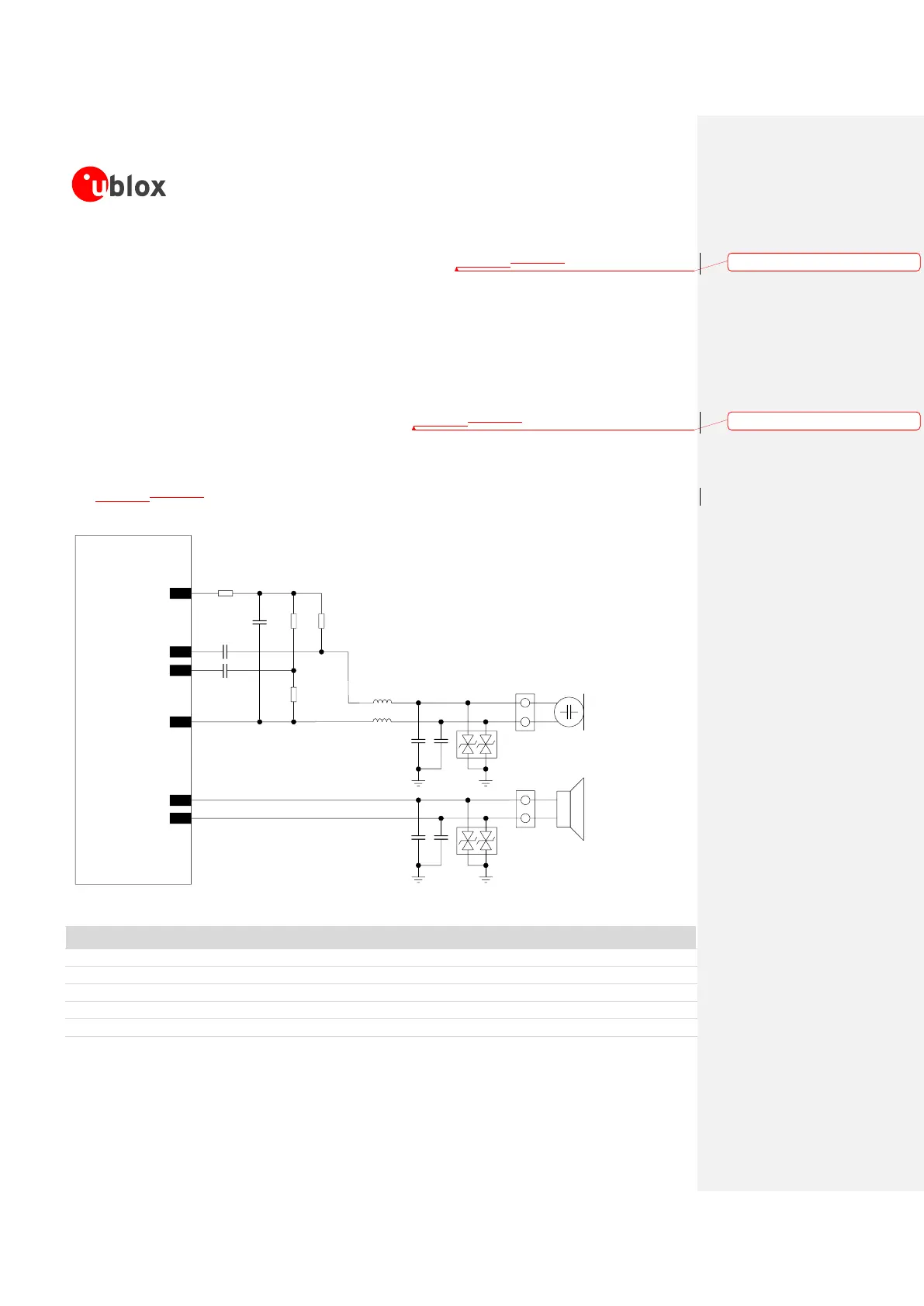
o Mount a 27 pF bypass capacitor (e.g. Murata GRM1555C1H270J) from each microphone
line to solid ground plane (C4 and C5 capacitors in Figure 57Figure 57).
Use a microphone designed for GSM applications, which typically has an internal built-in bypass
capacitor.
Connect the SPK_P and SPK_N analog downlink outputs directly to the receiver / speaker (which
resistance rating must be greater than 14 ).
Provide proper parts on each line connected to the receiver / speaker as noise and EMI improvments,
to minimize RF coupling, according to EMC requirements of the custom application.
o Mount a 27 pF bypass capacitor (e.g. Murata GRM1555C1H270J) from each speaker line to
solid ground plane (C6 and C7 capacitors in Figure 57Figure 57).
Provide additional ESD protection (e.g. EPCOS CA05P4S14THSG varistor array) if the analog audio
lines will be externally accessible on the application device, according to EMC/ESD requirements of the
custom application. Mount the protection close to an accessible point of the line (D1 and D2 in
Figure 57Figure 57).
SARA-G350
49
MIC_P
R1
R2 R4
44
SPK_P
48
MIC_N
45
SPK_N
R3
C1
46
MIC_BIAS
47
MIC_GND
C2
C3
D2
D1
C6 C7
L2
L1
C5C4
SPK
Speaker
Connector
J2
Microphone
Connector
MIC
J1
Figure 57: Analog audio interface headset and handset mode application circuit
Part Number – Manufacturer
10 µF Capacitor Ceramic X5R 0603 20% 6.3 V
GRM188R60J106ME47 – Murata
100 nF Capacitor Ceramic X7R 0402 10% 16 V
GRM155R71C104KA88 – Murata
27 pF Capacitor Ceramic C0G 0402 5% 25 V
GRM1555C1H270JA01 – Murata
Low Capacitance ESD Protection
USB0002RP or USB0002DP – AVX
Formatted: English (U.S.)
Formatted: English (U.S.)
 Loading...