SARA-G3 series - System Integration Manual
UBX-13000995 - R06 Objective Specification System description
Page 55 of 218
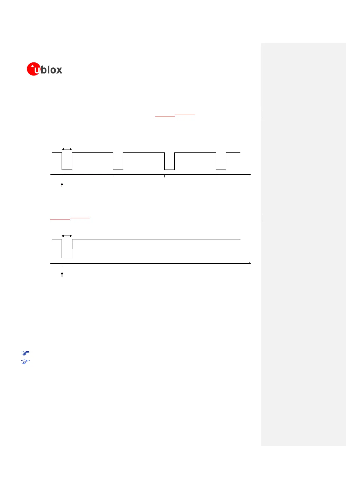
RI signal behavior
The RI module output line is set by default to the OFF state (high level) at UART initialization. Then,
during an incoming call, the RI line is switched from the OFF state to the ON state with a 4:1 duty
cycle and a 5 s period (ON for 1 s, OFF for 4 s, see Figure 17Figure 17), until the DTE attached to
the module sends the ATA string and the module accepts the incoming data call. The RING string sent
by the module (DCE) to the serial port at constant time intervals is not correlated with the switch of the
RI line to the ON state.
Figure 17: RI behavior during an incoming call
The RI line can notify an SMS arrival. When the SMS arrives, the RI line switches from OFF to ON for
1 s (see Figure 18Figure 18), if the feature is enabled by the proper AT command (refer to the
u-blox
AT Commands Manual
[2], AT+CNMI command).
Figure 18: RI behavior at SMS arrival
This behavior allows the DTE to stay in power saving mode until the DCE related event requests service.
For SMS arrival, if several events coincidently occur or in quick succession each event independently
triggers the RI line, although the line will not be deactivated between each event. As a result, the RI line
may stay to ON for more than 1 s.
If an incoming call is answered within less than 1 s (with ATA or if auto-answering is set to ATS0=1)
than the RI line is set to OFF earlier.
As a result:
RI line monitoring cannot be used by the DTE to determine the number of received SMSes.
For multiple events (incoming call plus SMS received), the RI line cannot be used to discriminate
the two events, but the DTE must rely on the subsequent URCs and interrogate the DCE with the
proper commands.
1s
time [s]
151050
RI ON
RI OFF
Call incomes
1s
time [s]
151050
RI ON
RI OFF
Call incomes
 Loading...