8 of 62 0319 IH-1679
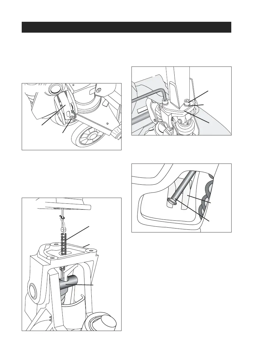
III. HANDLE INSTALLATION
1. Remove handle from protective
wrapping.
2. Loosen set screw (140) on crank link
(139H). (See Figure 7)
3. Remove 3 hex screws (H109) and 3
spring washers (H110) from bottom of
handle.
4. Feed Wire, Chain and Pin (H107) on
bottom of handle through center of
base (103) and axle (109). (See Figure 8)
5. Attach handle to base (103) using 3
hex screws (H109) and 3 spring washers
(H110) and tighten with Hex Wrench
provided. (See Figure 9)
6. While raising crank link (139H), slide pin
of rod and chain (H107) into crank link
groove. (See Figure 10)
REFERENCE PARTS DIAGRAMS
PAGES 16-19
Set Screw
(140)
(139H)
Axle
(109)
H107
103
Hex
Screw
(H109)
(103)
Spring
Washer
(H110)
Crank
Link
(139H)
H107
ASSEMBLY INSTRUCTIONS CONTINUED
Figure 7
Figure 8
Figure 9
Figure 10
 Loading...