USER GUIDE
Cutout Dimensions 1
u-line.com
SAFETY • INSTALLATION & INTEGRATION • OPERATING INSTRUCTIONS • MAINTENANCE • SERVICE
Cutout Dimensions
PREPARE SITE
Your U-Line product has been designed for either free-
standing or built-in installation. When built-in, your unit
does not require additional air space for top, sides, or
rear. However, the front grille must NOT be obstructed,
and clearance is required for an electrical and water
connection in the rear.
CAUTION
!
Units can NOT be installed behind a closed
cabinet door.
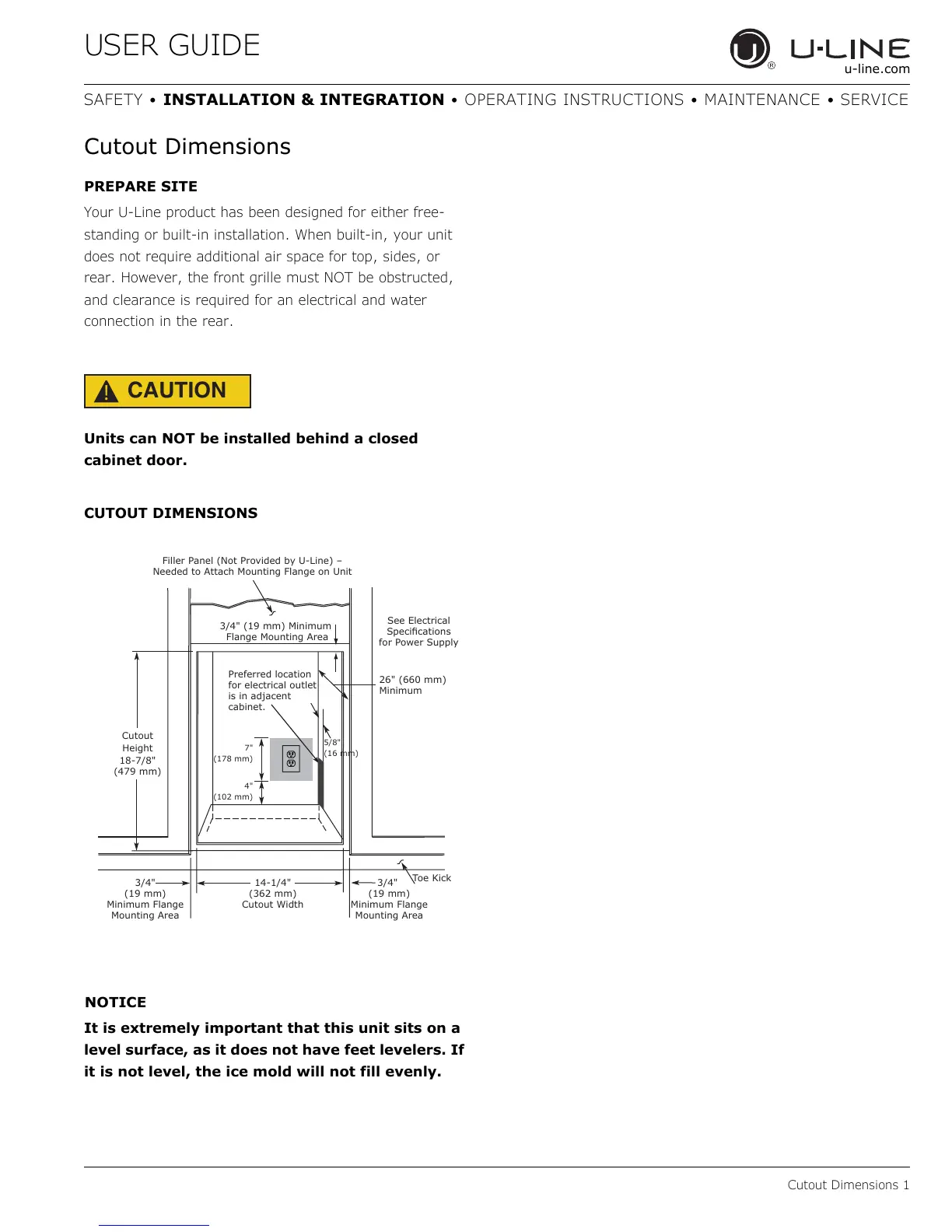
CUTOUT DIMENSIONS
It is extremely important that this unit sits on a
level surface, as it does not have feet levelers. If
it is not level, the ice mold will not fill evenly.
Cutout
Height
18-7/8"
(479 mm)
26" (660 mm)
Minimum
See Electrical
6SHFLɟFDWLRQV
for Power Supply
Filler Panel (Not Provided by U-Line) –
Needed to Attach Mounting Flange on Unit
Toe Kick
14-1/4"
(362 mm)
Cutout Width
3/4"
(19 mm)
Minimum Flange
Mounting Area
3/4" (19 mm) Minimum
Flange Mounting Area
3/4"
(19 mm)
Minimum Flange
Mounting Area
4"
(102 mm)
7"
(178 mm)
Preferred location
for electrical outlet
LVLQDGMDFHQW
cabinet.
5/8"
(16 mm)