USER GUIDE
Troubleshooting - Extended 7
u-line.com
SAFETY • INSTALLATION & INTEGRATION • OPERATING INSTRUCTIONS • MAINTENANCE • SERVICE
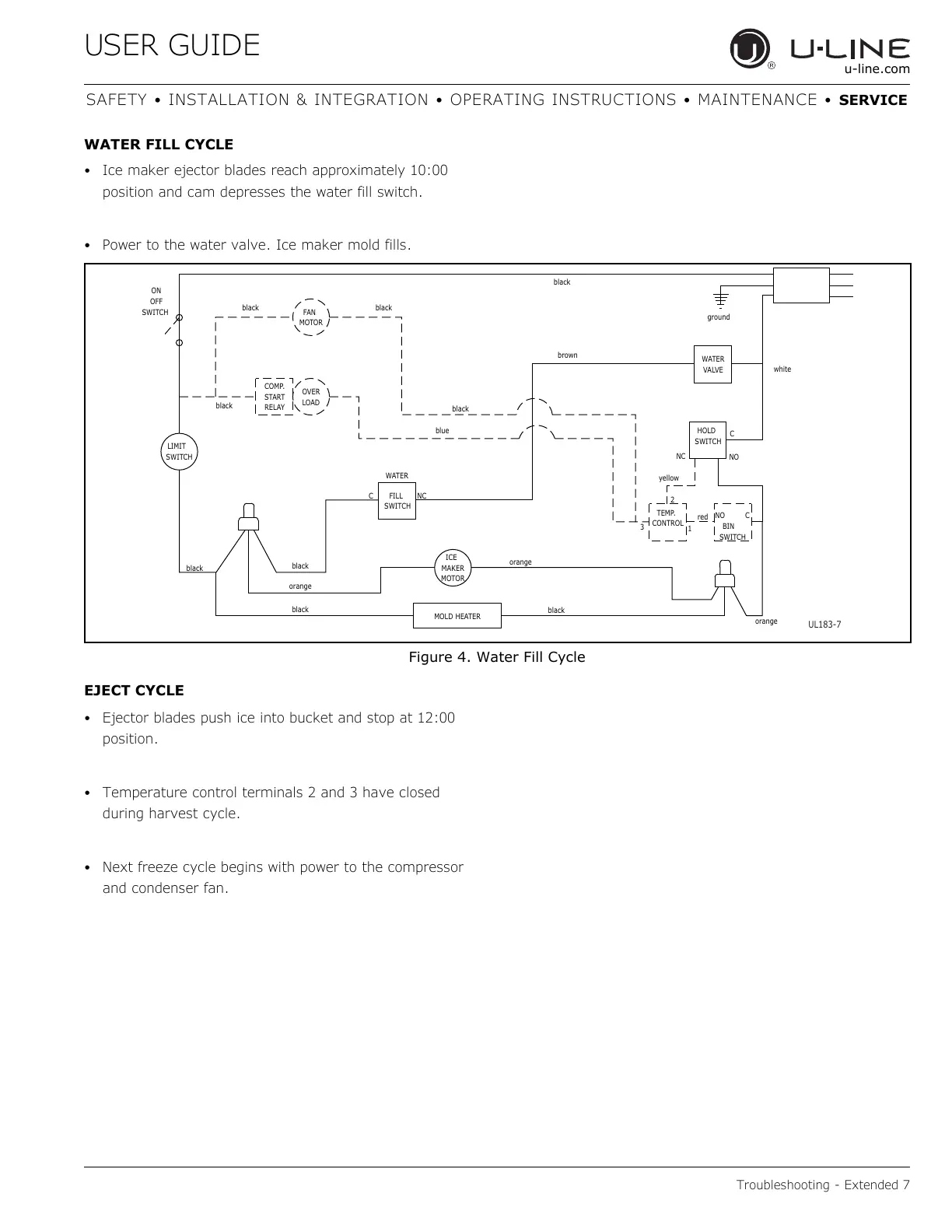
WATER FILL CYCLE
• Ice maker ejector blades reach approximately 10:00
position and cam depresses the water fill switch.
• Power to the water valve. Ice maker mold fills.
Figure 4. Water Fill Cycle
EJECT CYCLE
• Ejector blades push ice into bucket and stop at 12:00
position.
• Temperature control terminals 2 and 3 have closed
during harvest cycle.
• Next freeze cycle begins with power to the compressor
and condenser fan.
SWITCH
LIMIT
orange
black
black
black
MOTOR
MAKER
ICE
MOLD HEATER
WATER
SWITCH
FILL
C
NC
MOTOR
FAN
LOAD
OVER
black
RELAY
START
COMP.
SWITCH
OFF
ON
black
black
blue
black
CONTROL
TEMP.
NC
black
orange
3
yellow
2
orange
SWITCH
BIN
red
NO
1
C
NO
brown
black
white
C
SWITCH
HOLD
VALVE
WATER
ground
UL183-7
 Loading...