Part # 3052000 (09/16/09)Page 12
Installation Instructions for
Cuisine Back Risers.
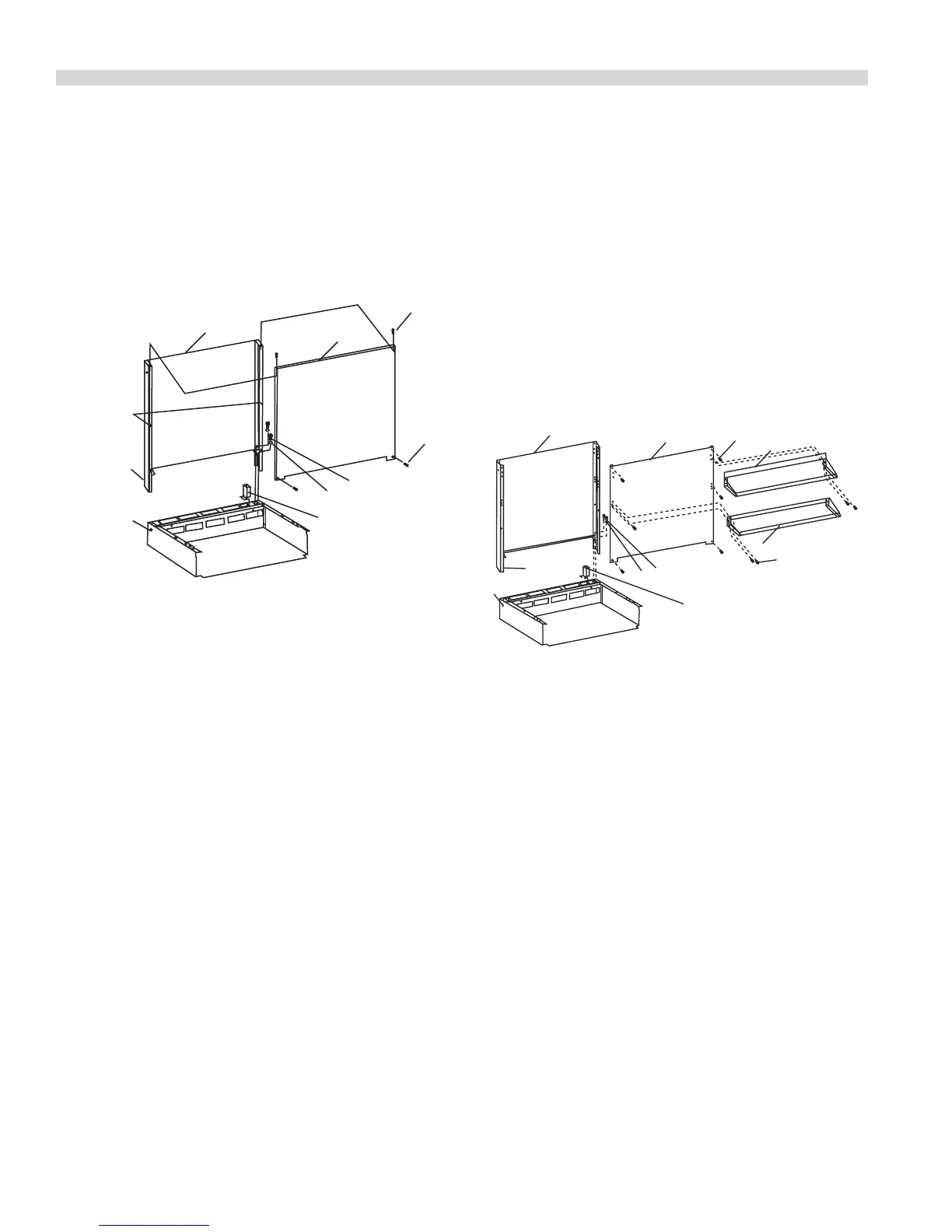
Double Deck Risers
Figure 2
Shoulder
Bolts
2
"x"
7
6
5
5
4
3
1
Oven Flue Riser
Optional right or
left Side
1. Remove four 5/16 hex bolts and at washers from top
rear of unit.
2. Remove four #10 x 1 1/4” long sheet metal screws (Item 5)
from top and lower front corners of front panel. Remove
front panel by lifting upwards and pulling outward to
clear heads of shoulder bolts axed to uprights (Item 2).
3. With back panel, (3), still attached to the uprights, (2),
drop the uprights into the rectangular openings at the
rear of the range.
4. Fasten the uprights, (2), to the range with four, 5/16” x 18
bolts and at washers, (Item 6 & 7) removed in step one.
5. If the range is in a battery line-up fastens units together
at hold marked “X” with 1/4-20 bolts, nuts and washers.
6. Reattach the front panel by placing notches in back of
the front panel over heads of shoulder bolts and pulling
panel down until the top of the front panel rests on top
of uprights. This will allow shoulder bolts to lock panel
in-place. Re-install sheet metal screws (Item 5) previously
removed.
INSTALLATION Continued
Single Deck Risers:
Follow instructions above for double-deck backriser but
as there are no shoulder bolts involved in the single deck
assembly, the installation and removal of the front panel only
comprises assembly and disassembly of the four #10 x 1 1/4”
long sheet metal screws (Item 5).
Installation Instructions For Cuisine Single
And Double Deck High Shelves
Figure 3
9
10
8
5
4
6
7
3
2
Oven Flue Riser
Optional right or
left side
1
"X"
1. Remove four 5/16” x 18 hex bolts and at washers from
top rear of unit (Item 6 & 7).
2. Remove four (4) 1/4-20 locking acorn nuts securing shelf
(Item 9). Remove shelf.
3. Remove (6) #10 sheet metal screws (Item 5) that ax
front panel (Item 4) to uprights (Item 2).
4. With back panel (3) still attached to uprights (2), drop the
uprights into the rectangular openings at the rear of the
range.
5. Fasten the uprights (2) to the range with four (4) 5/16” x
18 bolts and at washers previously removed.
6. If the appliance is in a battery line-up, fasten unit
together at hold marked “X” with 1/4 - 20 bolts, nuts and
washers.


 To Next Page