Part # 3052000 (09/16/09) Page 13
7. Reattach the front panel by rst aligning clearance holes
with studs in uprights and then re-installing sheet metal
screws (Item 5) previously removed.
8. After installing front panel install shelf (Item 8) by
hooking the top of shelf over the top of the front panel.
Threaded studs on uprights will pass through clearance
holes on rear of shelf. Fasten shelf to studs via 1/4 - 20
locking acorn nuts provided (Item 9).
9. For double deck shelves, mount the lower shelf (one
with at back and no upper hook) to uprights through
front panel via locking nuts (Item 9) provided to 1/4” – 20
threaded studs on uprights.
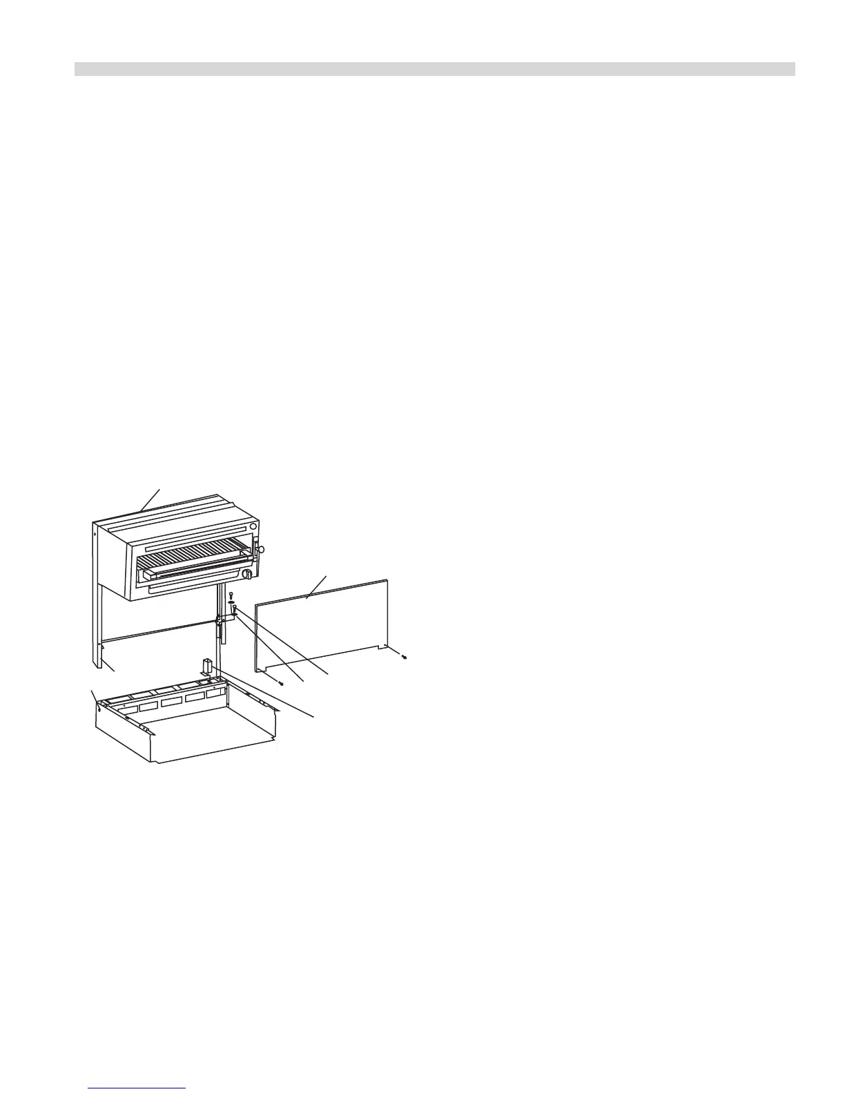
Installation Instructions For Cuisine
Salamander or Cheese Melter
Figure 4
2
"X"
Oven Flue Riser
Optional right or
left side
7
6
4
3
1
1. Remove four 5/16 x 18 hex bolts and at washers (Items 6
& 7) from rear top of unit.
2. Remove front panel, (4), by removing two, (2), sheet
metal screws from the underside of the salamander or
cheesemelter.
3. With back panel, (3), still attached to the uprights, (2),
drop the uprights into the rectangular openings at the
rear of the range.
4. Fasten the uprights (2), to the range with four, (4) 5/16” x
18 and at washers, (6 & 7) removed previously.
5. If the range is in a battery line-up, fasten units together at
hole marked “X” with 1/4 - 20 bolts, nuts and washers.
6. Reattach the front panel, (4) to the salamander or
Cheesemelter with sheet metal screws previously
removed.
Statutory Regulations
The installation of this appliance must be carried out by
a competent person and in accordance with the relevant
regulations, codes of practice and the related publications of
the country of destination.
Gas Supply
The local gas authority should be consulted at the
installation planning stage in order to establish the
availability of an adequate supply of gas and to ensure
that the meter is adequate for the required ow rate. The
pipe work from the meter to the appliances must be of an
appropriate size. Where a number of appliances are installed
in a battery, no more than ve should be served by any one
supply pipe.
All xed (non-mobile) appliances MUST be tted with a
manual gas cock-upstream of the appliance to provide a
means of isolation for servicing or cleaning purposes. A
union or similar means of disconnection must be provided
between the gas cock and the appliance.
A manually operable valve must be tted to the gas supply
to the kitchen to enable it to be isolated in a emergency.
Wherever the practical, this shall be located either outside
the kitchen or near to an exit in a readily accessible position.
Where it is not practical to do this, an automatic isolation
valve system shall be tted which can be operated from a
readily accessible position near to the exit.
At locations where the manual isolation valve is tted or
the automatic system can be reset a notice MUST be tted
stating:
“ALL DOWNSTREAM BURNER AND PILOT VALVES MUST
BE TURNED OFF PRIOR TO ATTEMPTING TO RESTORE THE
SUPPLY AFTER EXTENDED SHUT OFF, PURGE BEFORE
RESTORING GAS.”
INSTALLATION Continued