MIA-M10Q-Integration manual
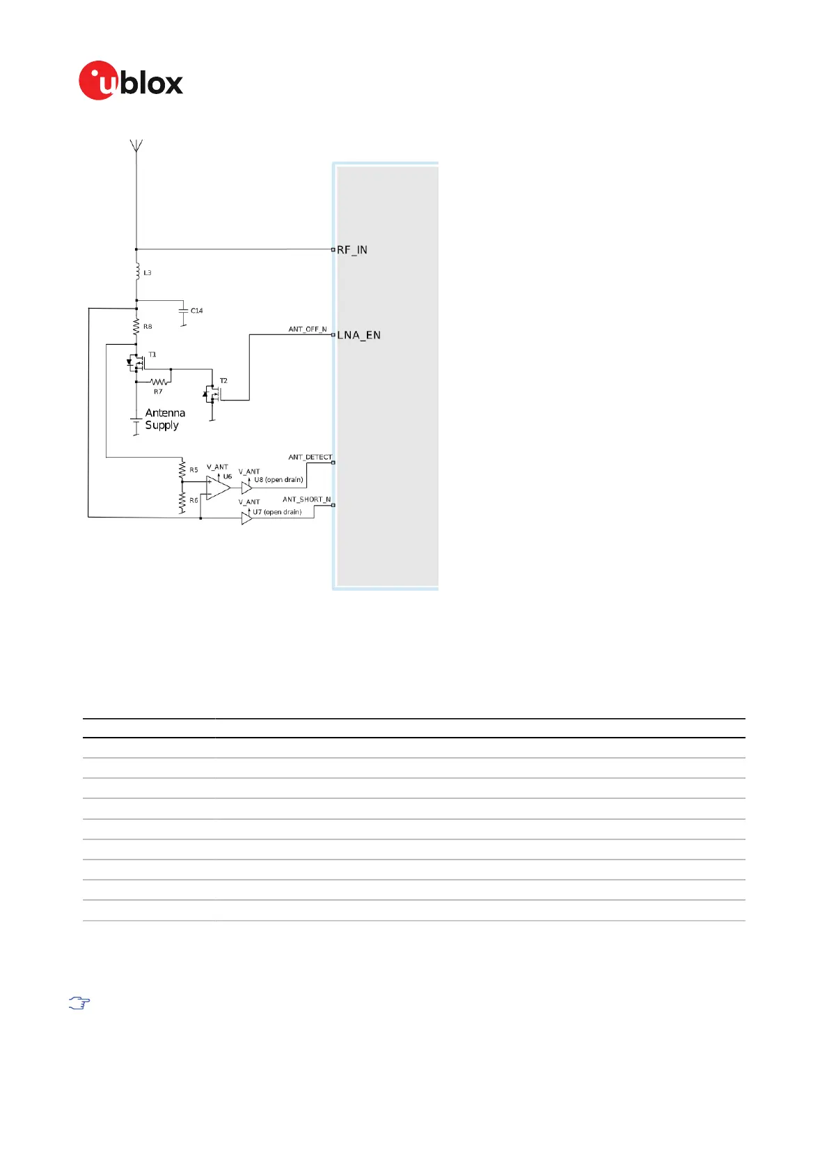
Figure 10: MIA-M10Q three-pin antenna supervisor
Table 15 presents a list of the external components required for implementing the three-pin antenna
supervisor design in Figure 10. Refer to External components for the recommended parts and
specification.
Part Description
C14 Filtering capacitor
L3 DC infeed inductor
T1, T2 p-channel, n-channel MOSFET acting as a switch to control the antenna supply
U6 Comparator (op-amp)
U7, U8 Open drain buffers to shift voltage levels
R7 Passive pull-up to control T1
R8 Current limiter in the event of a short circuit
R5 Defines the threshold of the comparator
R6 Defines the threshold of the comparator
Table 15: Components in antenna supervisor
The threshold voltage (V_REF) of the comparator is defined by R5 and R6. It can be calculated as:
V_REF = R6/(R6+R5)*V_ANT.
The open drain buffers shown in Figure 10 are not needed if V_ANT is the same voltage level
as V_IO.
UBX-21028173 - R01
2 Receiver functionality Page 28 of 89
C1-Public

 Loading...


