LEA-6 / NEO-6 / MAX-6 - Hardware Integration Manual
UBX-14054794 Production Information Design-in
Page 49 of 85
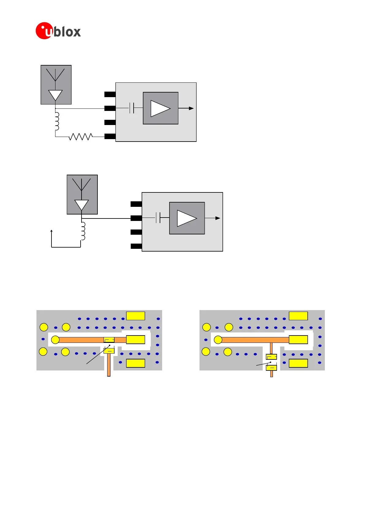
Low Noise Amplifier
Active Antenna
RF_IN
VCC_RF
GND
GND
10
R_BIAS
L
Figure 48: Internal antenna bias voltage for active antennas
Low Noise Amplifier
Active Antenna
RF_IN
VCC_RF
GND
GND
External
antenna
supply
voltage
L
Figure 49: External antenna bias voltage for active antennas
For optimal performance, it is important to place the inductor as close to the microstrip as possible. Figure 50
illustrates the recommended layout and how it should not be done.
GND
Microstrip
GND
RF_IN
Antenna Supply Voltage
(e.g. VCC_RF)
Inductor L
GND
GND
Antenna Supply Voltage
(e.g. VCC_RF)
Inductor L
Microstrip
RF_IN
Good Bad
Figure 50: Recommended layout for connecting the antenna bias voltage for LEA-6M and NEO-6

 Loading...


