SARA-G3 and SARA-U2 series - System Integration Manual
UBX-13000995 - R26 System description
Page 34 of 217
The RTC has very low power consumption, but is highly temperature dependent. For example, at +25 °C with
the V_BCKP voltage equal to the typical output value, the current consumption is approximately 2 µA (see the
“Input characteristics of Supply/Power pins” table in the SARA-G3 series Data Sheet [1] and SARA-U2 series Data
Sheet [2] for the detailed specification), whereas at +70 °C and an equal voltage the current consumption
increases to 5-10 µA.
If V_BCKP is left unconnected and the module main voltage supply is removed from VCC, the RTC is supplied
from the bypass capacitor mounted inside the module. However, this capacitor is not able to provide a long
buffering time: within few milliseconds the voltage on V_BCKP will go below the valid range (1 V min). This has
no impact on cellular connectivity, as all the module functionalities do not rely on date and time setting.
1.5.3 Generic digital interfaces supply output (V_INT)
The same 1.8 V voltage domain used internally to supply the generic digital interfaces of SARA-G3 and SARA-U2
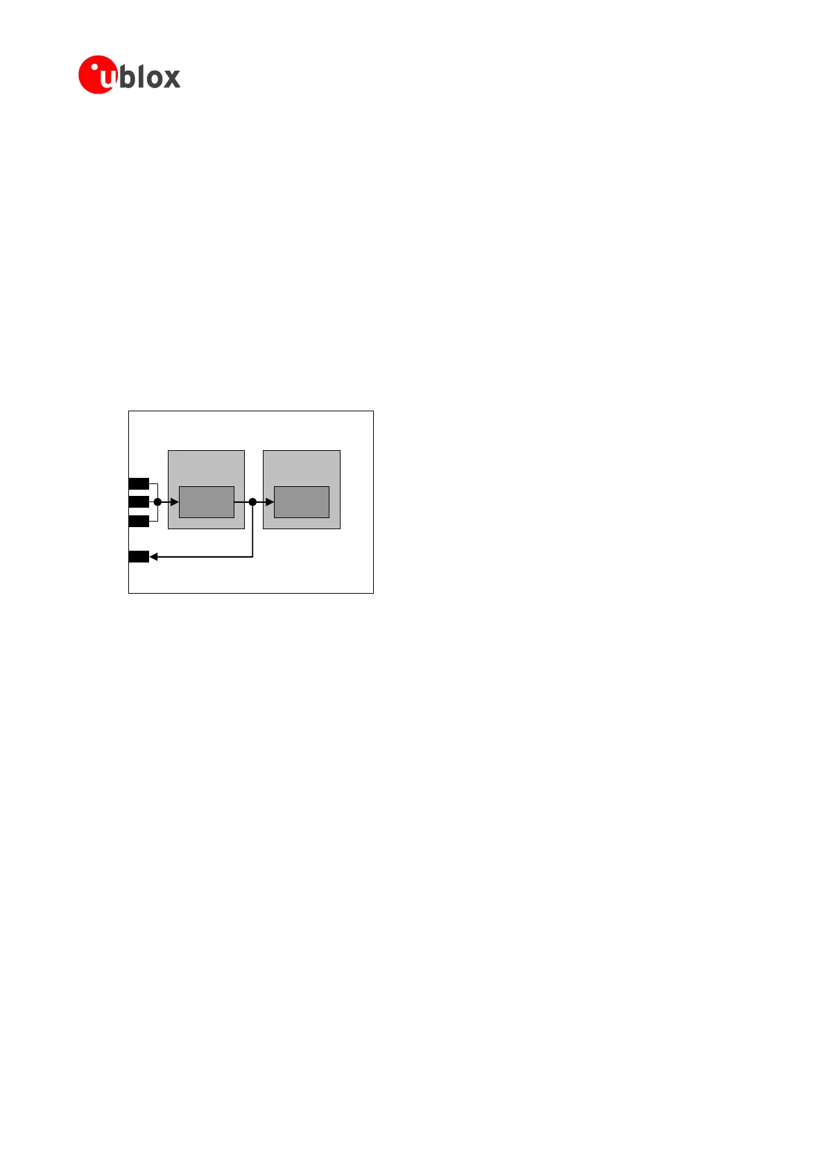
series modules is also available on the V_INT supply output pin, as described in Figure 19.
Baseband
Processor
51
VCC
52
VCC
53
VCC
4
V_INT
Switching
Step-Down
Digital I/O
Interfaces
Power
Management
SARA-G3 / SARA-U2 series
Figure 19: SARA-G3 and SARA-U2 series interfaces supply output (V_INT) simplified block diagram
The internal regulator that generates the V_INT supply is a switching step-down converter that is directly
supplied from VCC. The voltage regulator output is set to 1.8 V (typical) when the module is switched on and it
is disabled when the module is switched off.
The switching regulator operates in Pulse Width Modulation (PWM) for greater efficiency at high output loads
when the module is in active mode or in connected mode. When the module is in low power idle mode between
paging periods and with power saving configuration enabled by the appropriate AT command, it automatically
switches to Pulse Frequency Modulation (PFM) for greater efficiency at low output loads. See the u-blox AT
Commands Manual [3], +UPSV command.

 Loading...


