SARA-G3 and SARA-U2 series - System Integration Manual
UBX-13000995 - R26 System description
Page 13 of 217
1.2 Architecture
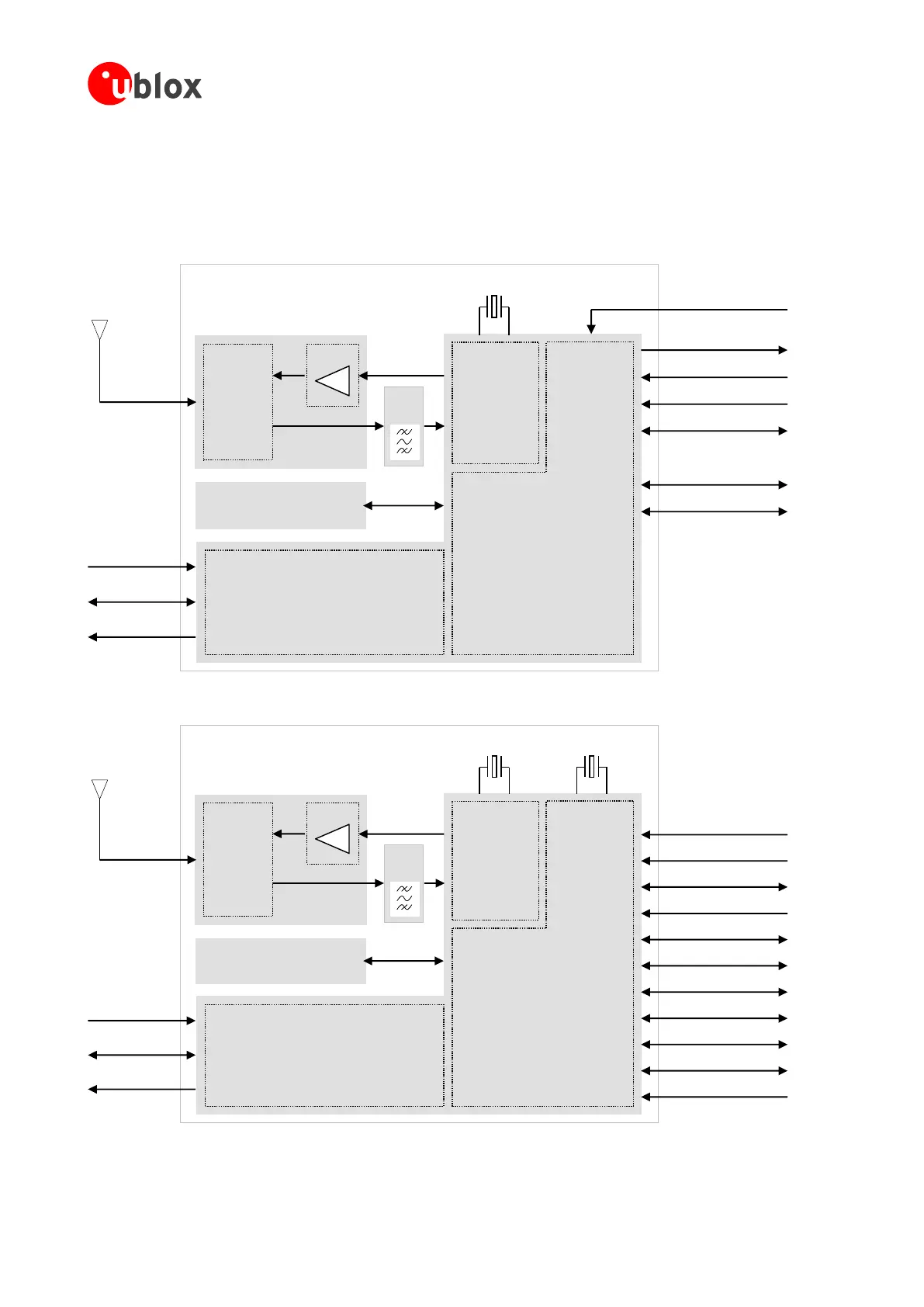
Figure 1 summarizes the architecture of the SARA-G300 and SARA-G310 modules, while Figure 2 summarizes
the architecture of the SARA-G340 and SARA-G350 modules, illustrating the internal blocks of the modules,
consisting of the RF, Baseband and Power Management main sections and the available interfaces.
Memory
V_BCKP (RTC)
V_INT (I/O)
32 kHz
26 MHz
RF
Transceiver
Power
Management
ANT
SAW
Filter
Switch
VCC (Supply)
32 kHz
Auxiliary UART
SIM
UART
Power-On
Reset
Cellular
BaseBand
Processor
PA
Figure 1: SARA-G300 and SARA-G310 modules block diagram
Memory
V_BCKP (RTC)
V_INT (I/O)
26 MHz
32.768 kHz
RF
Transceiver
Power
Management
Cellular
BaseBand
Processor
ANT
SAW
Filter
Switch
PA
VCC (Supply)
Auxiliary UART
DDC (for GNSS)
SIM Card Detection
SIM
UART
Power-On
Reset
Digital Audio
Analog Audio
GPIO
Antenna Detection
Figure 2: SARA-G340 and SARA-G350 modules block diagram

 Loading...


