SARA-G3 and SARA-U2 series - System Integration Manual
UBX-13000995 - R26 System description
Page 14 of 217
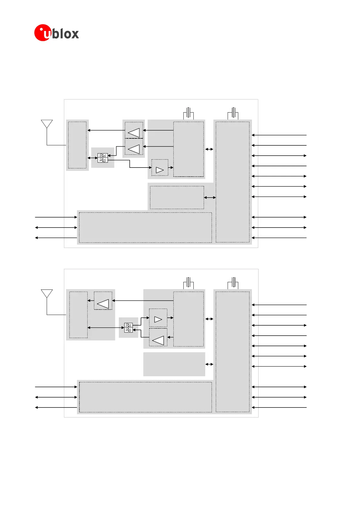
Figure 3 shows the architecture of the SARA-U201 modules, Figure 4 summarizes the architecture of the SARA-
U260 and SARA-U270 modules, while Figure 5 summarizes the architecture of the SARA-U280 modules,
illustrating the internal blocks of the modules, consisting of the RF, Baseband and Power Management main
sections and the available interfaces.
Memory
V_BCKP (RTC)
V_INT (I/O)
RF
transceiver
Power
Management
Cellular
BaseBand
Processor
ANT
VCC (Supply)
USB
DDC (I
2
C) / AUX UART
SIM card detection
SIM
UART
Power-On
Reset
Digital audio (I
2
S)
GPIO
Antenna detection
26 MHz
Duplexers
Filters
Switch
2G PA
32 kHz
LNAs
3G PA
Figure 3: SARA-U201 block diagram
Memory
V_BCKP (RTC)
V_INT (I/O)
RF
transceiver
Power
Management
Cellular
BaseBand
Processor
ANT
VCC (Supply)
USB
DDC (I
2
C)
SIM card detection
SIM
UART
Power-On
Reset
Digital audio (I
2
S)
GPIO
Antenna detection
3G PA
26 MHz
Duplexer
Filter
Switch
2G PA
LNA
32 kHz
Figure 4: SARA-U260 and SARA-U270 modules block diagram

 Loading...


