SARA-R4/N4 series - System Integration Manual
UBX-16029218 - R11 Design-in Page 109 of 157
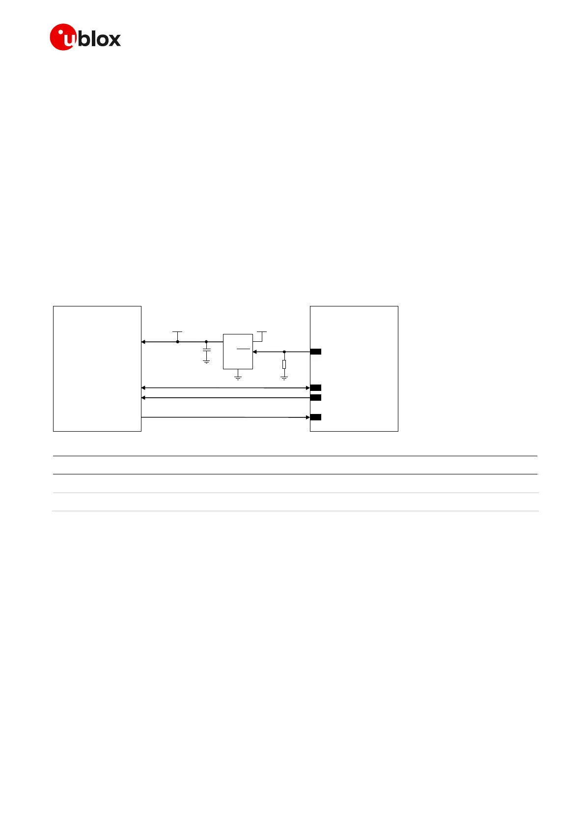
Connection with u-blox 1.8 V GNSS receivers
Figure 51 shows an application circuit for connecting the cellular module to a u-blox 1.8 V GNSS receiver:
The SDA and SCL pins of the cellular module are directly connected to the related pins of the u-blox
1.8 V GNSS receiver. External pull-up resistors are not needed, as they are already integrated in the
cellular module.
The GPIO2 pin is connected to the active-high enable pin of the voltage regulator that supplies the u-
blox 1.8 V GNSS receiver providing the “GNSS supply enable” function. A pull-down resistor is provided
to avoid a switch on of the positioning receiver when the cellular module is switched off or in the reset
state.
The GPIO3 pin is connected to the TXD1 pin of the u-blox 1.8 V GNSS receiver providing the additional
“GNSS Tx data ready” function.
IN
OUT
GND
GNSS LDO
Regulator
SHDN
u-blox GNSS
1.8 V receiver
SDA2
SCL2
VMAIN1V8
U1
23
GPIO2
SDA
SCL
C1
26
27
VCC
R1
GNSS supply enabled
SARA-R4/N4
(except ’00 ’,’0 1’ versions)
TxD1
GPIO3
24
GNSS dat a ready
Figure 51: Application circuit for connecting SARA-R4/N4 series modules to u-blox 1.8 V GNSS receivers
Part Number - Manufacturer
47 kΩ Resistor 0402 5% 0.1 W
RC0402JR-0747KL - Yageo Phycomp
Voltage Regulator for GNSS receiver
See GNSS receiver Hardware Integration Manual
Table 34: Components for connecting SARA-R4/N4 series modules to u-blox 1.8 V GNSS receivers
For additional guidelines regarding the design of applications with u-blox 1.8 V GNSS receivers, see the
Hardware Integration Manual of the u-blox GNSS receivers.
Connection with u-blox 3.0 V GNSS receivers
Figure 52 shows an application circuit for connecting the cellular module to a u-blox 3.0 V GNSS receiver:
As the SDA and SCL pins of the cellular module are not tolerant up to 3.0 V, the connection to the
related I
2
C pins of the u-blox 3.0 V GNSS receiver must be provided using a suitable I
2
C-bus Bidirectional
Voltage Translator (e.g. TI TCA9406, which additionally provides the partial power down feature so that
 Loading...


