16
to protect the LED. Otherwise, it will burn out!
In the following connection schematic, you will see the picture shown "+" "-"
In the wiring diagram, the longer pin (the curved pin) represents anode, the opposite one is
cathode.
5v
0v
5v
0v
5v
0v
5v
0v
5v
0v
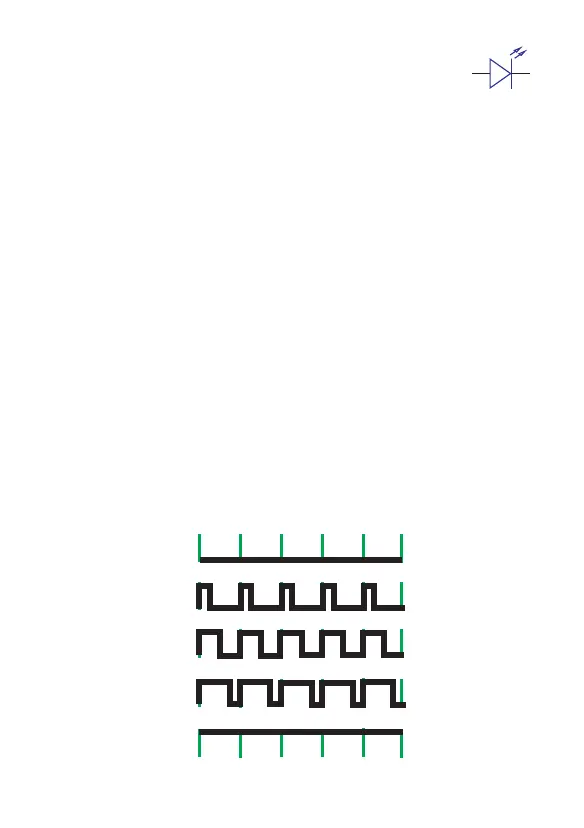
Pulse Width Modulation
0% Duty Cycle-analogWrite(0)
25% Duty Cycle-analogWrite(64)
50% Duty Cycle-analogWrite(127)
75% Duty Cycle-analogWrite(191)
100% Duty Cycle-analogWrite(255)
+
-
In the first step experiment we blink the onboard LED by tuning it on and off, the brightness of
LED can't be changed. So in the second step we will use PWM technique to adjust the brightness.
Pulse Width Modulation, or PWM, is a technique for getting analog results with digital means.
Digital control is used to create a square wave, a signal switched between on and off. This on-off
pattern can simulate voltages in between full on (5 Volts) and off (0 Volts) by changing the portion
of the time the signal spends on versus the time that the signal spends off. The duration of "on
time" is called the pulse width. To get varying analog values, you change, or modulate, that pulse
width. If you repeat this on-off pattern fast enough with an LED for example, the result is as if the
signal is a steady voltage between 0 and 5v controlling the brightness of the LED.
In the diagram below, the green lines represent regular time period. This duration or period is
the inverse of the PWM frequency. In other words, with Arduino's PWM frequency at about 500Hz,
the green lines would measure 2 milliseconds each. A call to analog Write () is on a scale of 0 - 255,
such that analog Write (255) requests a 100% duty cycle (always on), and analog Write (127) is a
50% duty cycle (on half the time) for example.
 Loading...