56
Lesson 22 LED bar graph display
Overview
In this lesson, you will learn how to control a LED bar graph in a row
Components Required
Name Qty Name Qty
UNO R3 or MEGA 2560 1 10KΩ Potentiometer 1
220Ω Resistor 1 LED Bar Graph 1
Breadboard 1 DuPont Wire 15
Component Introduction
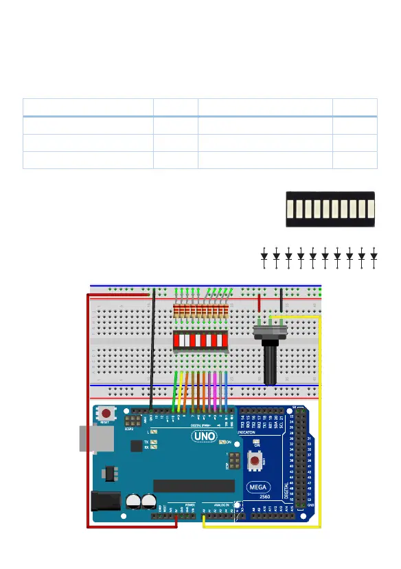
The bar graph is made of 10 independent LEDs in a row. Internal
schematic diagram for the LED bar graph shows in the right
picture. In this lesson, we will use a potentiometer to change
the input voltage of an analog pin. Then Arduino read the
voltage and display the voltage level on the LED bar display.
Wiring Diagram
1 2 3 4 5 6 7 8 9 10
20 19 18 17 16 15 14 13 12 11
A B C D E F G H I J
 Loading...