21
Lesson 4 Controlling a RGB LED by PWM
Overview
In this lesson, you will master how to program the UNO R3 or MEGA 2560 board for RGB
LED control and make RGB LED emits a variety of colors.
Components Required
Name Qty Name Qty
UNO R3 or MEGA 2560 1 Ω Resistor 3
RGB LED 1 DuPont Wire 4
Breadboard 1
Component Introduction
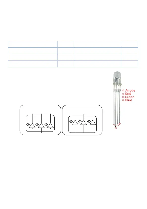
A RGB LED also known as Tri-color LED consists of three LEDs with a red,
a green and a blue light. These three colored LEDs are capable of
producing any color. It uses a four-wire connection with one common
lead (anode or cathode). These LEDs can have either common anode or
common cathode leads.
What we used in this experiment is the common anode RGB LED. The longest pin is the
common anode of three LEDs. The pin is connected to the +5V pin from the Arduino, and the
three remaining pins are connected to the Arduino's D9, D10, D11 pins through a current
limiting resistor.
In this way, we can control the color of RGB LED by 3-channels PWM signal.
blue
green
red
blue
green
red
Common Anode
RG B LED
Common Cathode
RG B LED
220
 Loading...